Keysight 5500 SPM Components
5
Keysight 5500 SPM User’s Guide
5-19
The signals are all passed through the box when the switches are in the
OUT position and the signals are all accessible from the IN or OUT
BNC's. If a switch is in the IN position, the signal on the OUT BNC is
the signal from the source and the connection between the IN BNC and
the OUT BNC is broken along with the connection through the box.
This allows for some external modification of the signal. The modified
signal would then be fed into the system using the IN BNC. The source
of the signal is from the Controller for all outputs and from either the
microscope electronics or the AC Mode controller for all of the inputs.
Breakout Box Connections
It is important to connect the breakout box correctly as shown in
.
To access the low voltage ports of the breakout box, connect one end of
a low voltage DB-44 cable to the front panel of the AFM controller.
Connect the other end of the cable to the N9744A connector labeled
Controller
. Connect one end of a second DB-44 cable (included with
the breakout box) to the N9744A connector labeled
Microscope
.
Connect the other end of the second cable to the connector labeled
Controller
on the first microscope component in the series
configuration. For example, this could be a MAC or AC mode
controller, or possibly the Head Electronics Box.
To access the high voltage ports of the breakout box, connect one end of
a high voltage DB-9 cable to the front panel of the AFM controller.
Connect the other end of the cable to the appropriate 9-pin connector
located on the side of the N9744A breakout box. Connect one end of a
second DB-9 cable (included with the breakout box) to the second 9-pin
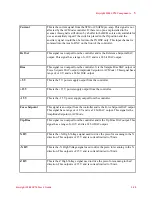
Y HV
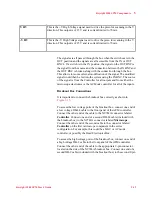
This is the +Y High Voltage signal used to drive the piezo for scanning in the Y
direction. This output is ±215 V and is current limited to 70 mA.
-Y HV
This is the -Y High Voltage signal used to drive the piezo for scanning in the Y
direction. This output is ±215 V and is current limited to 70 mA.

