Keysight 5500 SPM Components
5
Keysight 5500 SPM User’s Guide
5-17
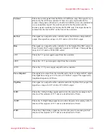
Table 1
List of signals and descriptions for AFM controller breakout
box
Signal
Description
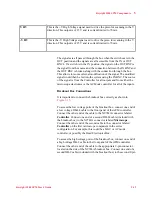
Error Signal
This is the servo signal from the Head Electronics Box to the controller for
AFM/STM. This signal is the photo detector A-B signal with the force setpoint
subtracted in AFM mode or the tunneling current in STM mode. If the breakout
box is placed between the AC Mode controller and the AFM controller and AC
Mode is
On,
then the signal will be the Amplitude signal from the AC Mode
controller. This signal is the Amplitude of the cantilever minus the Amplitude
setpoint. This input has a range of ±10 V.
Friction
This is the LFM signal from the Electronics box to the controller for AFM. This
signal is the photo detector C-D signal. If the breakout box is placed between the
AC Mode controller and the AFM controller and AC Mode is
On
, then the signal
will be the Phase signal from the AC Mode controller. This input has a range of
±10 V.
VEC
This is the potential signal from the PicoStat (Potentiostat) board if the
microscope has the electrochemistry option. If there is no electrochemistry
option, this is a floating input into the AFM controller and can be used as an
auxiliary data input channel. This input is displayed by the software with units of
volts. This signal is not affected by the presence of the AC Mode controller in the
system. This input has a range of ±10 V.
IEC
This is the current signal from the PicoStat (Potentiostat) board if the microscope
has the electrochemistry option. If there is no electrochemistry option, this is a
floating input into the AFM controller and can be used as an auxiliary data input
channel. This input is displayed by the software with units of current. This signal
is not affected by the presence of the AC Mode controller in the system. This
input has a range of ±10 V.


