


Additional Imaging Modes
5
Keysight 5500 SPM User’s Guide
5-23
4
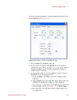
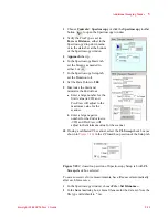
Set the Interleave Gain to
x1
or
x2
. Higher gains may cause the servo
to oscillate.
5
Set the Interleave Stop At value above
95 %
.
Setting the Stop At value too low can cause the tip-sample
interactions to dampen out the MFM data. Setting it too high can
cause the sensitivity of the tip to drop.
6
Set the Delay to
100 ms
.
7
Set the Pull Away to
200 nm
.
8
DAC to Change should be set to
None
.
The Delay parameter is a time delay prior to the beginning of the sweep
for the interleave channel. After clicking the Start button, the tip will
move to the Start location, then the system will pause the Delay time,
allowing the system to stabilize.
The Pull Away parameter sets the distance the tip is pulled away from
the surface to initiate the changes in the drive frequency and the drive
amplitude. Adjust Pull Away from between 100 and 200 nm to optimize
the image.
Begin imaging:
1
Initiate an approach:
a
In the Scan and Motor window, click the
Motor
tab.
b
Set the Stop At (%) to specify the percentage of total oscillation
that represents “contact,” typically
85-90 %
.
c
Click the
Approach
button in PicoView’s toolbar. The system
will raise the sample until the amplitude is damped to the Stop At
percentage.
2
In the Servo window, set the I Gain and P Gain to
5 %
. These gains
dictate how quickly the system will react to changes in amplitude.
3
In the Scan and Motor window’s
Scan
tab, enter:
a
Scan Speed of
1-2
ln/s.
b
Resolution of
512
.
c
Scan Size (in microns).
d
X Offset and/or Y Offset values to set the center of the scan.