MAC III
5
Keysight 5500 SPM User’s Guide
5-21
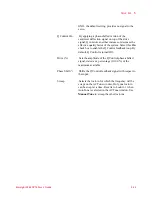
Optimize shifts the phase signal to maximize the X Component 2 (i.e.,
to maximize contrast).
X Component 2 and Phase 2 are routed to the Aux 1 and Aux 2 outputs,
respectively, for monitoring. To view changes in the EFM signal, choose
Aux 1 in the Realtime Images window.
KFM
In KFM Mode, Lock-in 1 is used to drive the cantilever, with the
Deflection channel as its Input. Lock-in 2 provides an AC tip bias, also
with the Deflection channel as its Input. A DC bias is provided by an
internal servo mechanism to counter electrostatic forces on the tip.
NOTE
For KFM mode, the Bias switch on the back of the Head Electronics
Box must be set to
Tip
.


