


MAC III
5
Keysight 5500 SPM User’s Guide
5-5
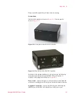
cable between the MICROSCOPE connector on the HEB and the 44-pin
connector on the microscope base.
AFM Controller Connection
Connect the longer DB44 cable from
the CONTROLLER connector on the MAC III to the PicoSPM II
connector on the AFM Controller.
BNC 1 and 2
These connectors are user configured outputs for
custom applications.
AUX
The AUX connector has the drive output from each lock-in, a
drive-in that can be summed into each lock-in, and an auxiliary input to
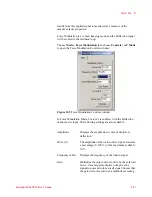
each lock-in. The pin-out diagram is shown in
Figure 11-3
AUX Connector pin-out diagram