AC Modes
5
Keysight 5500 SPM User’s Guide
5-8
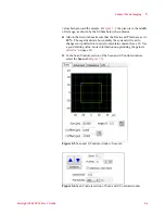
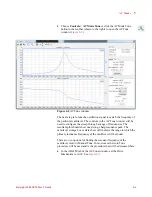
and drag the Scan box in the graph on the Scan tab to adjust the scan
size and location.
21
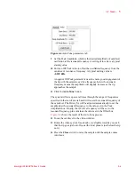
In the Realtime Images window, make sure that
Topography
and
Deflection
are displayed.
22
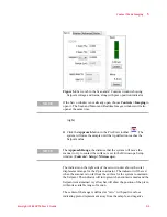
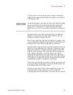
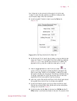
In the Scan Controls section, click the
Down
blue arrow to initiate a
scan starting at the top of the grid. Click the
Up
blue arrow to initiate
the scan from the bottom up. The image maps will begin to be
rendered in the Realtime Images window.
As the tip moves across the first scan line, the system will adjust the
voltage on the z-piezo to maintain constant amplitude (as specified by
the Setpoint voltage).
For each pixel, the system will record and plot the error signal (the
amount the oscillation amplitude would deviate from the Setpoint
voltage as the Amplitude Image (in volts).
The correction signal (the voltage that the system applies to the z piezo
to maintain the amplitude) is scaled by the Z piezo sensitivity and
plotted as topography (in nanometers).
At the end of each scan line the system will “retrace” the line to the
beginning of the scan.
Depending on the Frames setting in the Scan Controls section, the
system will either scan once and stop, or it will scan infinitely,
overwriting the last scan each time. You can also specify a specific
number of scans to complete.
To stop the scan cycle, click the red
STOP
circle that will replace the
Up or Down arrow when you start a scan.
Constant Height Mode
AC Mode imaging can be completed using either Constant Amplitude
mode, as described above, or Constant Height mode. In Constant Height
mode the tip remains in the same horizontal plane throughout the scan
(it does oscillate, but the center of that oscillation stays in plane). The
servo gains are set very low so that the system effectively does not react
to changes in amplitude.
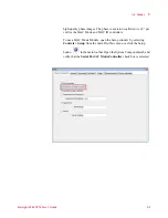
Constant Height Mode should only be used for very flat samples. To
image in Constant Height mode, in the Servo window set the I and P
gains to 0.1 %. This system will only very slowly adjust the z-piezo in

