Closed-Loop Scanners
5
Keysight 5500 SPM User’s Guide
5-10
19
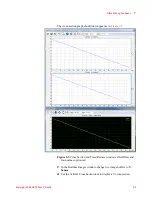
Adjust the
Y Sensor
values:
a
Adjust the Offset to shift the line up or down until the left end is
close to
-10 V
.
b
Adjust the Gain to adjust the slope until the right end of the line is
close to
+10 V
. Note this will take longer for the Y axis as is
slower than the X axis.
20
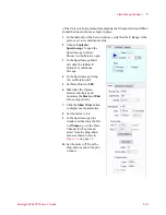
In the CL section of the Advanced tab of the Scan and Motor
window, select the
Enable
check box. The scanner will now function
in closed-loop mode.
21
Withdraw
the tip.
22
Save the new Scanner Setup parameters.
a
In the Scanner Setup window, choose
File > Save As
.
b
Enter a filename.
c
Click
OK
.
23
Place a calibration grating on the standard sample plate and mount
the plate on the microscope.
24
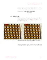
Align the grating in both the X and Y axes.
25
Perform all the Contact Mode imaging steps described in
to achieve a good image of the grating.
26
Adjust the Sensitivity of the X sensor:
a
In the Realtime Images window, choose
Tools > Horizontal
Cross Section
. Place the cross-section tool across a set of
features.
b
Set markers in the cross section window to measure the
dimension across several features of known width.
c
Use the equation below to adjust the Sensitivity value:
d
Image the features again and verify that the measured width
matches the actual width.
27
Repeat the step above with the
Vertical Cross Section
tool to set the
Sensitivity of the Y sensor.
The sensitivity ratio is the ratio of the closed loop sensor sensitivity to
the open loop sensor sensitivity, and affects the forward correction
feature. Open loop calibration can be performed for a small scan range
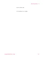
NewSensitivity
CurrentSensitivit y Kno
wnSize
MeasuredSize
--------------------------------------------------------------------------------------
=


