42
KATANA S610M Inverter Specialized for Elevator Manual
Function Code
Name
Setting Range
Factory Default Value
and then enter the calculated values
(
F01.05
~
F01.09
)
by following previous formulas of resistance and
inductance. Please ensure all the parameters are accurately set.
Since the no-load current of asynchronous motor identified in static state is not as accurate as that in
rotary state, F01.09 (no-load current )could be manually modified to a smaller value, for example 1-2A, if
the elevator causes a feeling of falling when starting and stopping during operation. The value to be
decreased could be bigger if the no-load current is higher.
1.
If auto tuning is unsuccessful, error E024 will be reported.
F01.17
Motor-overload protection factor setting
20.0
~
110.0%
100.0
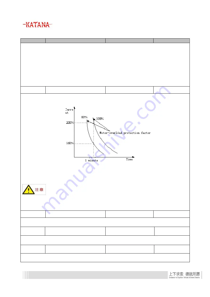
For effective overload protection for different motor models, it is necessary to adjust the permitted max.
output current of the inverter, as shown in Figure 2-3:
Figure 2-3 Motor-overload protection factor setting
The adjusted value can be set by users. Under same circumstances, if quick overload protection for motor is
required, F01.17 should be set smaller, and vice versa.
Attentions:
When the rated current of the motor does not match with that of the controller, overload protection
for the motor can be realized by setting F01.17.
F01.18
Oscillation inhibition factor
0
~
100
20
Under V/F control, this function can be adjusted to prevent motor oscillation.
F01.19
Gain compensation coefficient of SVC
slip frequency
50.0
%
~250.0%
100.0%
Applied to gain compensation of SVC slip frequency.
F01.20
Tuning coefficient of synchronous
motor
50
%
~100%
80%
Applied to parameters tuning of synchronous motor. This parameter can be increased when magnetic pole


