Console Configuration
The
Patch Output Display
Eclipse User Guide
V1.0/1
223/ 380
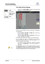
The Patch Output Display
1.
Select the
PATCH OUTPUT
display by pressing the
PATCH OUT
button on the UTILITIES panel.
2.
Make sure that the
PATCH
tab is selected:
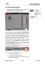
This grid operates in a very similar to the
PATCH INPUT
.
However, this time you are patching an output fader (Aux,
Group, Master, Matrix or Monitor) to a destination (on the right).
Connections are indicated by a yellow triangle ( ) or box ( )
within the grid. Connections made from a Smart Fader VCA are
indicated with green boxes . A column of LEDs to the right of
the output labels shows if an output is muted (red).
As before you can view the patching from either the
DESK
(Fader strips 1 to 48) or
S.PANEL
(Smart Panel strips 1 to 48).
The
PATCH OUTPUT
grid is
only
used to connect Output
channels to destinations, therefore you cannot select an Input
or VCA fader as patching is not allowed.
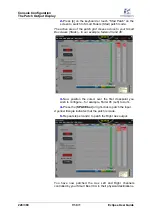
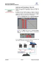
At the bottom of the display you will see the Output Label and
metering for the selected destination:
The row of boxes above the faders indicates:
•
- the Output is not patched.
•
- the Output is patched (direct patch).
•
- the fader is a Smart Bus VCA. Press [
s
] to reveal the
component channel patching.
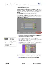
Patch OUT
(UTILITIES)
“
GRID -> Patch
Output
”
[
F12
]


