Chapter 5:
Console Operation
Output Channels
:
Signal
Flow
Eclipse User Guide
V1.0/1
151/ 380
Output Channels
Just like inputs, all mix busses must be assigned to the surface,
either to a Fader Strip or Smart Panel control. This creates an
Output channel which provides level, mute, cue, etc. for the bus
output.
Signal Flow
All output channels provide the following:
•
Delay – assignable from a pool of 48 delay resources.
•
Pre-fader Insert (external device, floating DSP resource
or internal effects bay)
•
Pan
•
Main level, Mute and Cue
•
Post-fader Insert (external device, floating DSP resource
or internal effects bay)
Signal Processing
To apply signal processing you can either insert one of 16
internal “floating” DSP paths, or route the mix bus to a physical
output. Every output of a
UM8-PO
card provides output
processing (Compressor, Gate, 8-band Parametric EQ, 31-
band Graphic EQ and Delay).
Note that there is an important difference between inserting a
floating DSP path, and using a processed output. Inserted
processing will be applied to everything downstream of the
output channel, whereas processing from a UM8 output card
applies only to that physical output. This allows you to patch
say a single matrix bus to multiple outputs each with its own
delay time, graphic EQ, etc.
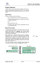
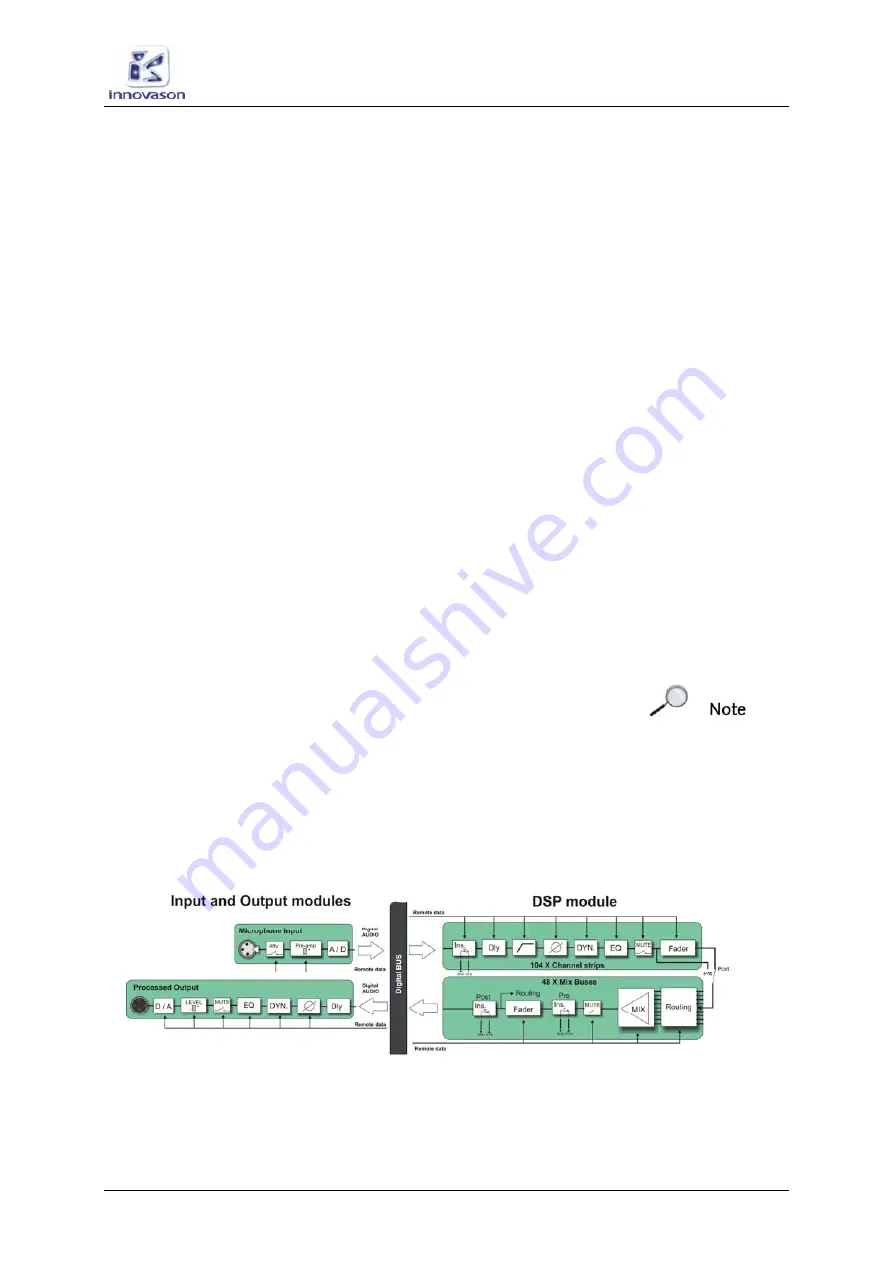
The following diagram shows the division between processing
on the I/O cards and processing on
Eclipse
’s DSP module:

