


402
Controller Enclosure Modules
Installing the BBU
1. Unpack the new BBU. Save the shipping material for transporting the used BBU to the
disposal facility.
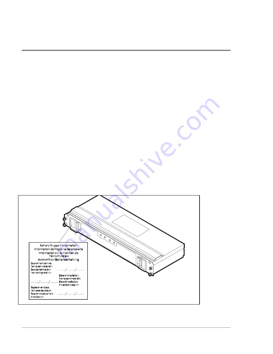
2. Fill in the following information on the “Battery Support Information” label on the front
of the battery. See
Figure 102
.
a. Record the current date on the blank line next to “Date of Installation.”
b. Record the expiration date (two years from the current date) on the line next to
“Replacement Date.”
3. Slide the new BBU into the slot and tighten the screws. See
Figure 101
.
4. Install the controller enclosure front cover. See
"Front Cover Removal/Replacement" on
page 397
.
5. Allow the system to run up to 7 hours to properly charge the BBU. The Full Charge LEDs
will flash while the BBU is charging. When properly charged, both Full Charge LEDs on
the front of the BBU will remain on.
Figure 102
Battery Information Label
Summary of Contents for Surestore Disk Array 12h - And FC60
Page 16: ...16 ...
Page 36: ...36 Array Controller Enclosure Components Figure 9 Controller Enclosure Front View ...
Page 41: ...Array Controller Enclosure Components 41 Product Description Figure 13 Controller Fan Module ...
Page 44: ...44 Array Controller Enclosure Components Figure 15 Power Supply Fan Module ...
Page 68: ...68 Capacity Management Features ...
Page 117: ...Topologies for HP UX 117 Topology and Array Planning Figure 39 High Availability Topology ...
Page 122: ...122 Topologies for HP UX Figure 40 High Availability Distance and Capacity Topology ...
Page 126: ...126 Topologies for HP UX Figure 41 Campus Topology ...
Page 130: ...130 Topologies for HP UX Figure 43 Four Hosts Connected to Cascaded Switches ...
Page 142: ...142 Topologies for Windows NT and Windows 2000 ...
Page 158: ...158 Installing the Disk Array FC60 Figure 54 Enclosure EIA Positions for System E Racks ...
Page 161: ...Installing the Disk Enclosures 161 Installation Figure 56 Disk Enclosure Contents ...
Page 172: ...172 Installing the Controller Figure 62 Controller Enclosure Package Contents ...
Page 174: ...174 Installing the Controller Figure 63 Mounting the Controller Enclosure ...
Page 234: ...234 Adding Disk Enclosures to Increase Capacity ...
Page 274: ...274 Managing the Disk Array Using SAM Unassigned disks selected as hot spares ...
Page 345: ...HP UX Diagnostic Tools 345 5 HP UX DIAGNOSTIC TOOLS Overview 346 Support Tools Manager 347 ...
Page 350: ...350 Support Tools Manager Figure 90 mstm Interface Main Window ...
Page 358: ...358 Support Tools Manager ...
Page 440: ...440 FCC Statements USA Only ...
Page 466: ...466 Index ...