


Installing the Disk Enclosures
167
Inst
alla
tion
1.
Open the disk enclosure door.
2. Put on the ESD strap (provided with the accessories) and insert the end into the ESD
plug-in (D in
Figure 60
) near the upper left corner of the disk enclosure.
C
AUTION
Disks are fragile. Handle them carefully.
3. Remove the bagged disk from the disk pack.
C
AUTION
Do not touch exposed circuit board side of the disk module.
4. Remove the disk from the ESD bag, grasping the disk by its handle (B).
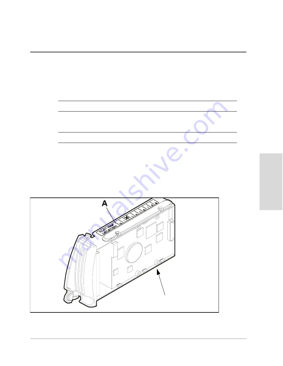
5. Using a pencil, mark an “X” on the Slot Location Map label (A in
Figure 61
), located on
the top of the disk module. This mark identifies the disk slot the disk module should be
installed in case it is removed. It is important to return a disk to its same location to
maintain disk module addressing used by some FC60 software applications.
Figure 61
Disk Module Slot Location Map Label
Do Not Touch
Summary of Contents for Surestore Disk Array 12h - And FC60
Page 16: ...16 ...
Page 36: ...36 Array Controller Enclosure Components Figure 9 Controller Enclosure Front View ...
Page 41: ...Array Controller Enclosure Components 41 Product Description Figure 13 Controller Fan Module ...
Page 44: ...44 Array Controller Enclosure Components Figure 15 Power Supply Fan Module ...
Page 68: ...68 Capacity Management Features ...
Page 117: ...Topologies for HP UX 117 Topology and Array Planning Figure 39 High Availability Topology ...
Page 122: ...122 Topologies for HP UX Figure 40 High Availability Distance and Capacity Topology ...
Page 126: ...126 Topologies for HP UX Figure 41 Campus Topology ...
Page 130: ...130 Topologies for HP UX Figure 43 Four Hosts Connected to Cascaded Switches ...
Page 142: ...142 Topologies for Windows NT and Windows 2000 ...
Page 158: ...158 Installing the Disk Array FC60 Figure 54 Enclosure EIA Positions for System E Racks ...
Page 161: ...Installing the Disk Enclosures 161 Installation Figure 56 Disk Enclosure Contents ...
Page 172: ...172 Installing the Controller Figure 62 Controller Enclosure Package Contents ...
Page 174: ...174 Installing the Controller Figure 63 Mounting the Controller Enclosure ...
Page 234: ...234 Adding Disk Enclosures to Increase Capacity ...
Page 274: ...274 Managing the Disk Array Using SAM Unassigned disks selected as hot spares ...
Page 345: ...HP UX Diagnostic Tools 345 5 HP UX DIAGNOSTIC TOOLS Overview 346 Support Tools Manager 347 ...
Page 350: ...350 Support Tools Manager Figure 90 mstm Interface Main Window ...
Page 358: ...358 Support Tools Manager ...
Page 440: ...440 FCC Statements USA Only ...
Page 466: ...466 Index ...