3-18
UR SERIES – COMMUNICATIONS GUIDE
CONFIGURING THE UR USING SCL
CHAPTER 3: IEC 61850 COMMUNICATION
3
•
Configuring addressing and timing parameters of GOOSE messages
•
Adding datasets for publishing GOOSE messages
•
Configuring GOOSE subscription
•
Configuring addressing and timing parameters for reports
•
Adding datasets for reports
•
Configuring command models and timeouts
The following conditions apply to ensure that the resulting configuration is not rejected by the UR device or EnerVista UR
Setup:
•
No elements in the IED element can be removed, added or reordered, except that DataSet, Private, and IEDName
elements can be added where allowed by the standard. IED element attributes can also be added. DataSet elements
must be added only in @Master/LLN0, and must not exceed the number supported. Private elements must only be
added to the IED element. The IED element attributes type and manufacturer must not be modified. The value of data
attributes that are not shown with a "C" in the R/W/C columns in the
Model implementation conformance statement
section on page 3-24 cannot have their value changed by the SCT.
•
The DataTypeTemplates element cannot be changed in a way that removes, adds, reorders, or changes properties of
data objects or data attributes, although the template id attributes can be changed provided it is done consistently
throughout the file so as to not affect the information model. EnumVal elements can be removed or reordered.
•
Unused SubNetwork, GSE, and Address elements in the Communications element can be omitted as long as one
remains; the settings corresponding omitted attributes are left at their factory default value. BitRate elements can be
added to SubNetwork elements, but do not affect the fixed UR bit rate. Note that Access point S1 is physical Ethernet
port 1, access point S2 is physical Ethernet port 2, and access point S3 is physical Ethernet port 3.
•
Some other additions/changes can be tolerated on import, but are not preserved on export
If the configuration generated by the SCT in the SCD is complete, the next step is to use it to program each of the IEDs. For
UR devices, there are several ways in which this can be done. A CID file can be sent directly to the UR device using any of
the supported file transfer protocols. CID files, which can be directly generated by some SCTs, are just the SCD with
configuration information not required by the target IED removed.
Alternatively, the SCD can be imported by EnerVista UR Setup, which generates URS files for each UR device that the SCD
contains, and the configuration in those URS files sent to the URs.
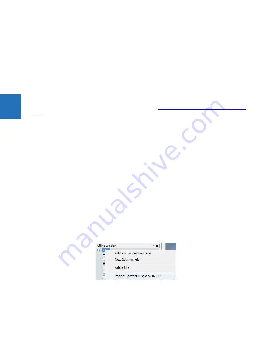
To import a SCD or CID into EnerVista UR Setup, right-click on either the Offline Window label or the
Files
label in the Offline
Window, select
Import Contents From SCD/CID
, and enter a name for a URS file for each of the IED configurations being
imported. The default URS file name is the IED name in the SCD/CID. For writing settings from the imported files to the UR
devices, connect to each UR device in the Online Window, and drag-and-drop the URS file in the Offline Window to the
appropriate UR device in the Online Window. When the SCD file has more than one UR device in it, the system prompts for
the name to use.
Figure 3-10: Importing a settings file
Note that there is no option to import IID files. This is because it is not called for in the standards and there is little need.
If the configuration generated by the SCT is not complete, which is typically the case, proceed as in the previous paragraph
to import the SCD/CID, complete the configuration in the URS files using EnerVista UR Setup, and then drag the URS files to
the UR devices.
For problems found during the commissioning stage that require a setting change, setting changes can be made using the
front panel, EnerVista UR Setup, or the SCT. Changes made at any level in the SCT/UR Setup/UR device chain can be
propagated down using the methods described in the preceding paragraphs. It is important that any changes made at a
Summary of Contents for UR series
Page 5: ...TABLE OF CONTENTS UR SERIES COMMUNICATIONS GUIDE v INDEX...
Page 6: ...vi UR SERIES COMMUNICATIONS GUIDE TABLE OF CONTENTS...
Page 20: ...1 14 UR SERIES COMMUNICATIONS GUIDE FOR FURTHER ASSISTANCE CHAPTER 1 INTRODUCTION 1...
Page 216: ...2 196 UR SERIES COMMUNICATIONS GUIDE MEMORY MAP CHAPTER 2 MODBUS COMMUNICATION 2...
Page 428: ...A 2 UR SERIES COMMUNICATIONS GUIDE REVISION HISTORY APPENDIX A MISCELLANEOUS A...


