EPSON AcuLaser C8500
Revision C
Chapter 4
Diagnostics
4-14
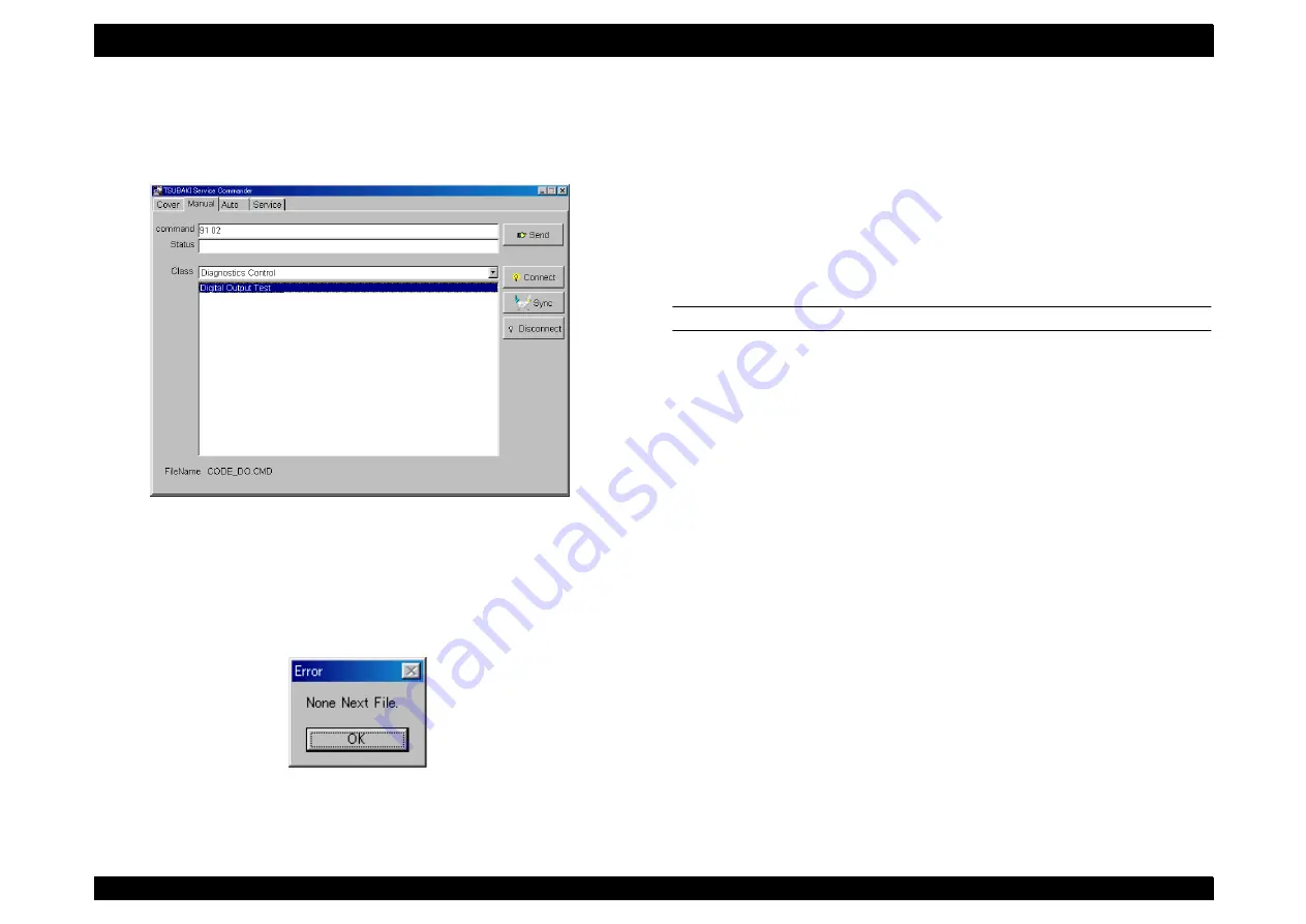
NOTE: Double clicking displays the command code in the [Command]
column, and also the parameter codes of the selected command
code if it has any having parameter codes.
7. As above, selecting a parameter code displays the parameter code
in the [Command] column. Double clicking when there are no
parameters causes an [Error] window to be displayed.
8. After completing command selection, click on the [Send] button to
send the command to be sent.
NOTE: To select the other commands without sending them, move the
cursor into the window for selecting parameters, click the right
button, and click on the [Go Back] button. This returns you to the
previous parameter.
9. For commands having a corresponding status, the status will be
displayed in the [Status] column in hex code.
NOTE: Before changing to another menu ([Auto] or [Service]), click on
the [Disconnect] button to disconnect communications.
DIRECT ENTRY FROM THE COMMAND COLUMN
[Procedure]
1. Connect DIAG TOOL with the printer, launch the diagnostics
commander.
2. Click on the [Manual] tab to display the Manual window.
3. Establish communications by connecting (See Section 4.2.4.2
4. Enter the command codes and the parameter codes in hex code
with a one-byte space between them in the [Command] column.
NOTE: Use regular ASCII characters for input.
5. After entering the command to be sent, click on the [Send] button to
send the command.
6. For a command with a corresponding status, the status is displayed
in the [Status] column in the hex codes.
NOTE: Before changing to another menu ([Auto] or [Service]), click on
the [Disconnect] button to disconnect communications.
Summary of Contents for AcuLaser C8500
Page 12: ......
Page 21: ...C H A P T E R 1 PRODUCTDESCRIPTIONS ...
Page 78: ...C H A P T E R 2 OPERATINGPRINCIPLES ...
Page 108: ...EPSON AcuLaser C8500 Revision C Operating Principles 2 31 Figure 2 38 Xerographics II ...
Page 110: ...EPSON AcuLaser C8500 Revision C Operating Principles 2 33 Figure 2 39 Development ...
Page 118: ...EPSON AcuLaser C8500 Revision C Operating Principles 2 41 Figure 2 45 Drive ...
Page 120: ...EPSON AcuLaser C8500 Revision C Operating Principles 2 43 Figure 2 46 Electrical ...
Page 153: ...C H A P T E R 3 DISASSEMBLY ASSEMBLY ADJUSTMENT ...
Page 269: ...C H A P T E R 4 DIAGNOSTICS ...
Page 353: ...C H A P T E R 5 TROUBLESHOOTING ...
Page 480: ...C H A P T E R 6 MAINTENANCE ...
Page 503: ...C H A P T E R 7 APPENDIX ...
Page 564: ......
Page 565: ......
Page 566: ......
Page 567: ......
Page 568: ......
Page 569: ......
Page 570: ......


