180
General Service and Replacing FRUs
2
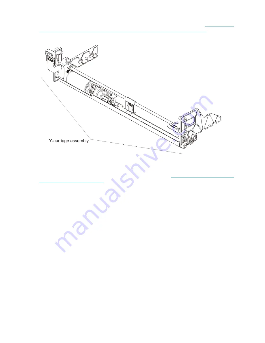
Separate the robot into the Y-carriage assembly and picker assembly. For details, see
Removing and
Replacing the Model 1 Picker Assembly from the Y-Carriage Assembly Inside the Library
on page 176.
(The instructions for removal are the same whether inside or outside of the library.)
3
Reassemble the new Y-carriage assembly and the picker assembly outside of the module.
4
Replace the robot in the library, following the complete instructions in
Installing the Model 1 and Model
2 Robot Assemblies in the Library
on page 171.
Model 1 robot
Summary of Contents for PowerVault ML6000
Page 1: ...w w w d e l l c o m s u p p o r t d e l l c o m MaintenanceGuide Dell PowerVault ML6000 ...
Page 14: ...xiv Tables ...
Page 18: ...xviii Figures ...
Page 452: ...434 Troubleshooting the Tape Library ...
Page 456: ...438 Library Drawings Library Rear View Figure 32 ML6020 Rear View ...
Page 468: ...450 Library Drawings Power Supplies Figure 49 Power Supplies ...
Page 477: ...PowerVault ML6000 Maintenance Guide 459 Figure 58 Electrical System 5U Library Control Module ...
Page 478: ...460 Library Drawings Figure 59 LCB Functions ...
Page 479: ...PowerVault ML6000 Maintenance Guide 461 ...
Page 482: ...464 Library Drawings Figure 64 Fan Control Board ...
Page 483: ...PowerVault ML6000 Maintenance Guide 465 Figure 65 Library Cables ...
Page 484: ...466 Library Drawings Figure 66 Library System Grounding ...
Page 485: ...PowerVault ML6000 Maintenance Guide 467 Figure 67 Library Power System ...
Page 486: ...468 Library Drawings ...
Page 494: ...476 Glossary Y axis Y position The vertical position of the library s robotic arm ...


