PowerVault ML6000 Maintenance Guide
119
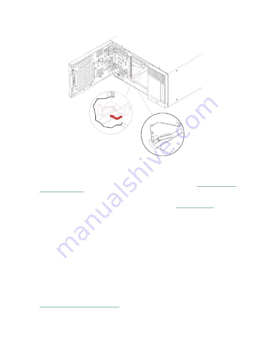
c. Gently release the robot assembly. It will lower to the bottom module of the library.
6
Close the module’s doors.
7
Install the remaining modules of your library (if any), following the instructions in
Installing Additional
Modules Into the Rack
on page 119.
8
Reinstall the tape drives, power supplies, and tape cartridges in the library.
9
Cable your library as necessary, following the instructions provided in
Cabling the Library
on page 22.
10
Power on the library.
Installing Additional Modules Into the Rack
All modules that you add to the rack must be positioned above the module that you previously installed,
since the bottom module must be secured to the rack-mount shelves (unless you decide to uninstall the
entire library from the rack and reconfigure it).
Required parts:
Rack ears, (4) M5 thumbscrews, (4) nut clips (if needed) or (4) cage nuts (if needed)
Explanation of parts:
Each rack ear contains two elongated holes, enabling you to fasten it to the rack
using the M5 thumbscrews and either the nut clips or cage nuts (or neither if your rack has threaded holes),
using the most accessible mounting holes.
1
If you are installing a module above a module that currently has a top cover, remove the top cover.
Similarly, if the module you are installing has a bottom cover, remove the bottom cover before installing
the module above another module in the rack. You need to make sure the library is “hollow” all the way
through with just one bottom cover on the lowest module and one top cover on the top module. See
Installing the New 9U Expansion Module
on page 64.
2
Determine where in the rack to install the nut clips (or cage nuts).
Model 2 tab
Model 1 tab
Summary of Contents for PowerVault ML6000
Page 1: ...w w w d e l l c o m s u p p o r t d e l l c o m MaintenanceGuide Dell PowerVault ML6000 ...
Page 14: ...xiv Tables ...
Page 18: ...xviii Figures ...
Page 452: ...434 Troubleshooting the Tape Library ...
Page 456: ...438 Library Drawings Library Rear View Figure 32 ML6020 Rear View ...
Page 468: ...450 Library Drawings Power Supplies Figure 49 Power Supplies ...
Page 477: ...PowerVault ML6000 Maintenance Guide 459 Figure 58 Electrical System 5U Library Control Module ...
Page 478: ...460 Library Drawings Figure 59 LCB Functions ...
Page 479: ...PowerVault ML6000 Maintenance Guide 461 ...
Page 482: ...464 Library Drawings Figure 64 Fan Control Board ...
Page 483: ...PowerVault ML6000 Maintenance Guide 465 Figure 65 Library Cables ...
Page 484: ...466 Library Drawings Figure 66 Library System Grounding ...
Page 485: ...PowerVault ML6000 Maintenance Guide 467 Figure 67 Library Power System ...
Page 486: ...468 Library Drawings ...
Page 494: ...476 Glossary Y axis Y position The vertical position of the library s robotic arm ...


