PowerVault ML6000 Maintenance Guide
163
4
Using your hands, remove the black cover plate on the back of the access door by squeezing it slightly
on both sides and pulling it toward you. Set it aside.
5
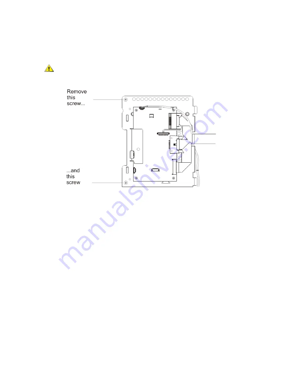
Remove the four cables that are attached to the operator panel.
6
Using the screwdriver, remove the two screws that secure the operator panel to the access door.
7
Remove the operator panel and replace it with the new one.
8
Using the screwdriver, tighten the screws to secure the new operator panel to the access door.
9
Reconnect the cables.
CAUTION
When removing the final screw, hold the operator panel to ensure it
doesn’t fall and become damaged.
Summary of Contents for PowerVault ML6000
Page 1: ...w w w d e l l c o m s u p p o r t d e l l c o m MaintenanceGuide Dell PowerVault ML6000 ...
Page 14: ...xiv Tables ...
Page 18: ...xviii Figures ...
Page 452: ...434 Troubleshooting the Tape Library ...
Page 456: ...438 Library Drawings Library Rear View Figure 32 ML6020 Rear View ...
Page 468: ...450 Library Drawings Power Supplies Figure 49 Power Supplies ...
Page 477: ...PowerVault ML6000 Maintenance Guide 459 Figure 58 Electrical System 5U Library Control Module ...
Page 478: ...460 Library Drawings Figure 59 LCB Functions ...
Page 479: ...PowerVault ML6000 Maintenance Guide 461 ...
Page 482: ...464 Library Drawings Figure 64 Fan Control Board ...
Page 483: ...PowerVault ML6000 Maintenance Guide 465 Figure 65 Library Cables ...
Page 484: ...466 Library Drawings Figure 66 Library System Grounding ...
Page 485: ...PowerVault ML6000 Maintenance Guide 467 Figure 67 Library Power System ...
Page 486: ...468 Library Drawings ...
Page 494: ...476 Glossary Y axis Y position The vertical position of the library s robotic arm ...


