MAX II
Bolt Tension Monitor
67
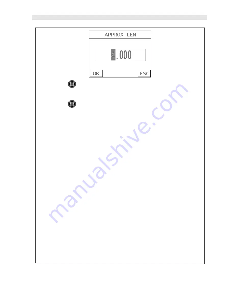
17) Press the
UP
and
DOWN
arrow keys multiple times using the left or
right button wheel to scroll the highlighted value.
18) Press the
LEFT
and
RIGHT
arrow keys multiple times using the left
button wheel to scroll the digit locations.
19) Repeat steps
17 & 18
until the
APPROX LEN
value is correctly displayed.
20) Press the
OK
key to set the
Approximate Length
and return to the menu
screen, or
ESC
to cancel entering the
Approximate Length
.
21) Use the
UP
and
DOWN
arrow keys to scroll through the sub menu items
until
AUTO SET
is highlighted.
Note:
Both the
Approximate Length
and
Auto Set
feature could have also been
set and activated using the
Hot Menu
Items and
Keypad Auto Set
button as
well. However, since we are already in the
Tab Menu
Items, it was just as easy
as returning to the
Hot Menu
Items screen.
22) Apply a drop of couplant to the bolt or transducer, and attach it to one end
of the bolt. Rotate the transducer clockwise and counter clockwise applying
a small amount of pressure to eliminate any excess couplant between the
transducer and bolt surface.
Be sure to always place the transducer in the
same location
.
This will help to eliminate any potential measurement errors
cause by changing the sound path.
Summary of Contents for MAX II
Page 2: ......
Page 7: ......
Page 8: ......
Page 54: ...Dakota Ultrasonics 46 Figure 6 Reflection in a bending bolt ...
Page 215: ......


