background image


12-2

Cisco Network Modules Hardware Installation Guide

OL-2485-20

Chapter 12      Connecting T1/E1 IMA Network Modules

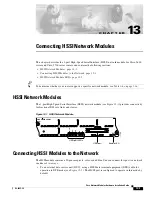
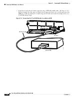
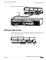
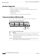
IMA Network Modules

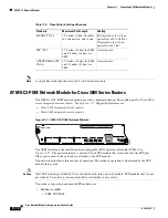
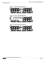
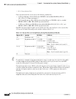
Figure 12-2 8-Channel IMA T1 Network Module

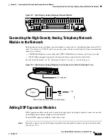
Figure 12-3 4-Channel IMA E1 Network Module

Figure 12-4 8-Channel IMA E1 Network Module

ATM-T1
8T1-IMA

17924

AL
LP
CD

AL
LP
CD

AL

T1-IMA 7

T1-IMA 6

T1-IMA 5

T1-IMA 4

T1-IMA 3

SEE MANUAL BEFORE
INSTALLATION

T1-IMA 2

T1-IMA 1

T1-IMA 0

LP
CD

AL
LP
CD

AL
LP
CD

AL
LP
CD

AL
LP
CD

AL
LP
CD

EN

ATM-E1
4E1-IMA

17923

E1-IMA 3

SEE MANUAL BEFORE INSTALLING NETWORK MODULE

E1-IMA 2

E1-IMA 1

E1-IMA 0

AL
LP
CD

AL
LP
CD

AL
LP
CD

AL
LP
CD

EN

ATM-E1
8E1-IMA

EN

17925

AL
LP
CD

AL
LP
CD

AL

E1-IMA 7

E1-IMA 6

E1-IMA 5

E1-IMA 4

E1-IMA 3

SEE MANUAL BEFORE
INSTALLATION

E1-IMA 2

E1-IMA 1

E1-IMA 0

LP
CD

AL
LP
CD

AL
LP
CD

AL
LP
CD

AL
LP
CD

AL
LP
CD

Summary of Contents for 3600 Series

Page 1: ...isco com Tel 408 526 4000 800 553 NETS 6387 Fax 408 526 4100 Cisco Network Modules Hardware Installation Guide For the Cisco 2600 Series Cisco 2800 Series Cisco 3600 Series Cisco 3700 Series and Cisco 3800 Series Routers and the Cisco MWR 1941 DC Mobile Wireless Edge Router Text Part Number OL 2485 20 ...

Page 2: ... try to correct the interference by using one or more of the following measures Turn the television or radio antenna until the interference stops Move the equipment to one side or the other of the television or radio Move the equipment farther away from the television or radio Plug the equipment into an outlet that is on a different circuit from the television or radio That is make certain the equ...

Page 3: ...sco Access Routers for instructions on installing network modules in your router See Chapter 3 through Chapter 29 for information about connecting network modules to the network See the software configuration guides for Cisco 2600 series Cisco 2800 series Cisco 3600 series Cisco 3700 series and Cisco 3800 series routers for an overview of network module configuration procedures and information on ...

Page 4: ...g that could result in equipment damage or loss of data Table 1 Document Conventions Convention Description boldface font Commands and keywords italic font Variables for which you supply values Keywords or arguments that appear within square brackets are optional x y z A choice of required keywords appears in braces separated by vertical bars You must select one screen font Examples of information...

Page 5: ...e schakelingen betrokken risico s en dient u op de hoogte te zijn van de standaard praktijken om ongelukken te voorkomen Voor een vertaling van de waarschuwingen die in deze publicatie verschijnen dient u de vertaalde veiligheidswaarschuwingen te raadplegen die bij dit apparaat worden geleverd Opmerking BEWAAR DEZE INSTRUCTIES Opmerking Deze documentatie dient gebruikt te worden in combinatie met ...

Page 6: ...brauch in Verbindung mit dem Installationshandbuch für Ihr Gerät bestimmt das dem Gerät beiliegt Entnehmen Sie bitte alle weiteren Informationen dem Handbuch Installations oder Konfigurationshandbuch o Ä für Ihr spezifisches Gerät Figyelem FONTOS BIZTONSÁGI ELÕÍRÁSOK Ez a figyelmezetõ jel veszélyre utal Sérülésveszélyt rejtõ helyzetben van Mielõtt bármely berendezésen munkát végezte legyen figyele...

Page 7: ...ção destina se a ser utilizada em conjunto com o manual de instalação incluído com o produto específico Consulte o manual de instalação o manual de configuração ou outra documentação adicional inclusa para obter mais informações Advertencia INSTRUCCIONES IMPORTANTES DE SEGURIDAD Este símbolo de aviso indica peligro Existe riesgo para su integridad física Antes de manipular cualquier equipo conside...

Page 8: ...e Installation Guide OL 2485 20 Preface Obtaining Documentation Obtaining Documentation Cisco documentation and additional literature are available on Cisco com This section explains the product documentation resources that Cisco offers ...

Page 9: ... regularly DVDs are available singly or by subscription Registered Cisco com users can order a Product Documentation DVD product number DOC DOCDVD or DOC DOCDVD SUB from Cisco Marketplace at the Product Documentation Store at this URL http www cisco com go marketplace docstore Ordering Documentation You must be a registered Cisco com user to access Cisco Marketplace Registered users may order Cisc...

Page 10: ...vulnerabilities quickly If you think that you have identified a vulnerability in a Cisco product contact PSIRT For emergencies only security alert cisco com An emergency is either a condition in which a system is under active attack or a condition for which a severe and urgent security vulnerability should be reported All other conditions are considered nonemergencies For nonemergencies psirt cisc...

Page 11: ... resolving technical issues with Cisco products and technologies The website is available 24 hours a day at this URL http www cisco com techsupport Access to all tools on the Cisco Technical Support Documentation website requires a Cisco com user ID and password If you have a valid service contract but do not have a user ID or password you can register at this URL http tools cisco com RPF register...

Page 12: ...ts to help keep your business operations running smoothly To open a service request by telephone use one of the following numbers Asia Pacific 61 2 8446 7411 Australia 1 800 805 227 EMEA 32 2 704 55 55 USA 1 800 553 2447 For a complete list of Cisco TAC contacts go to this URL http www cisco com techsupport contacts Definitions of Service Request Severity To ensure that all service requests are re...

Page 13: ...king training and certification titles Both new and experienced users will benefit from these publications For current Cisco Press titles and other information go to Cisco Press at this URL http www ciscopress com Internet Protocol Journal is a quarterly journal published by Cisco Systems for engineering professionals involved in designing developing and operating public and private internets and ...

Page 14: ...xiv Cisco Network Modules Hardware Installation Guide OL 2485 20 Preface Obtaining Additional Publications and Information ...

Page 15: ...ments page 1 30 Where to Go Next page 1 33 Introduction to Cisco Network Module Form Factors Cisco network modules are available in the following four different form factors to provide greater modularity and functionality for users Single wide network modules also called NM or NME see Figure 1 1 Extended single wide network modules also called NME X see Figure 1 2 Double wide network modules also ...

Page 16: ... the bottom slot only supports single wide modules On the Cisco 3745 router the double wide network module occupies two single wide slots and is supported by removing the midwall divider On Cisco 2851 and Cisco 3800 series routers network module slots must be set up properly before double wide network modules can be installed See Figure 1 3 for a sample double wide network module Figure 1 3 Sample...

Page 17: ...isco 2611 Cisco 2611XM Cisco 2612 Cisco 2613 Cisco 2620 Cisco 2620XM Cisco 2621 Cisco 2621XM Cisco 2650 Cisco 2650XM Cisco 2651 Cisco 2651XM and Cisco 2691 routers Note References to the Cisco 2600XM routers apply to the following routers Cisco 2610XM Cisco 2611XM Cisco 2620XM Cisco 2621XM Cisco 2650XM and Cisco 2651XM Cisco 2811 Cisco 2821 and Cisco 2851 routers Cisco 3600 series including the Ci...

Page 18: ... See Table 1 1 for information on the type and quantity of network module slots available on Cisco access routers 1 Network module slot 2 4 Network module slot 1 2 Network module slot 4 5 Network module slot 3 3 Network module slot 6 6 Network module slot 5 1 High speed WAN interface card slot 0 4 High speed WAN interface card slot 3 2 High speed WAN interface card slot 1 5 Extension module slot 3...

Page 19: ... not supported in standard network module slots on this platform 1 Extension module Slot 2 Extension module slots do not support other single wide network modules Cisco 3620 routers 2 Single wide Slot 0 slot 1 Does not support extension modules Cisco 3640 routers 4 Single wide Slot 0 slot 3 Does not support extension modules Cisco 3660 routers 6 Single wide Double wide Slot 1 slot 6 see Figure 1 5...

Page 20: ...uble wide network modules remove the slot divider See the Removing Slot Dividers section on page 2 12 Only one extension module can be installed per chassis 1 Double wide Extended double wide Slot 2 To install double wide network modules remove the slot divider See the Removing Slot Dividers section on page 2 12 Only one NM 36ESW network module bcan be installed per chassis Cisco 3845 routers 4 Si...

Page 21: ...modules Note Some combination voice data interface cards are supported on 1 or 2 slot network modules However interface card functionality is limited to either voice or data applications See Table 1 2 for more information Figure 1 7 Sample 1 Slot Network Module Figure 1 8 Sample 2 Slot Network Module For information on installing interface cards onto network modules see the Installing Cisco Interf...

Page 22: ...2A S Yes No No No No No WIC 1DSU 56K Yes No No No No No WIC 1DSU T1 Yes No No No No No WIC 1ADSL Yes No No No No No WIC 1ADSL I DG Yes No No No No No WIC 1SHDSL Yes No No No No No WIC 1AM Yes No No No No No WIC 2AM Yes No No No No No WIC 1AM V2 Yes No No No No No WIC 2AM V2 Yes No No No No No WIC 1AM V2 Yes No No No No No WIC 2AM V2 Yes No No No No No VWIC 1MFT G703 Data only No No No No No VWIC2 ...

Page 23: ... No Yes1 Yes1 No No VIC 2FXO No Yes No No No No VIC 2FXO M1 No Yes No No No No VIC 2FXO EU No Yes No No No No VIC 2FXO M2 No Yes No No No No VIC 2FXO M3 No Yes No No No No VIC2 2FXO No No Yes Yes No No VIC2 4FXO No No Yes Yes No No VIC 2E M No Yes No No No No VIC2 2E M No No Yes Yes No No VIC 2BRI S T TE No Yes No No No No VIC 2BRI NT TE No Yes No No No No VIC2 2BRI NT TE No No Yes Yes No No VIC 2...

Page 24: ... E3 NM 1A E3 NM 1A T3 E3 ATM optical Duplex or simplex SC 62 5 micron core with an optical loss of 0 to 9 dB Note Maximum path length of 2 km 1 24 miles all cables end to end NM 1A OC3 POM NM 1A OC3MM NM 1A OC3SMI NM 1A OC3SML NM 1A OC3MM EP NM 1A OC3SMI EP NM 1A OC3SML EP NM 1A OC3MM 1V NM 1A OC3SMI 1V NM 1A OC3SML 1V 50 micron core with optical loss of 7 dB Note Maximum path length of 2 km 1 24 ...

Page 25: ...2FE2W V2 NM 1FE1R2W NM 1FE1R2W V2 NM 1FE1CT1 NM 1FE2CT1 NM 1FE1CT1 CSU NM 1FE2CT1 CSU NM 1FE1CE1B NM 1FE1CE1U NM 1FE2CE1B NM 1FE2CE1U NM 16ESW NM 16ESW 1GIG NM 16ESW PWR NM 16ESW PWR 1GIG NM CE BP 20G K9 NM CE BP 40G K9 NM CE BP 80G K9 NM CE BP SCSI K9 NM CIDS K9 NM NAM NMD 36ESW NMD 36ESW 2GIG NMD 36ESW PWR NMD 36ESW PWR 2G NME 16ES 1G NME 16ES 1G P NME X 23ES 1G NME X 23ES 1G P NME XD 24ES 1S P ...

Page 26: ... 1G NME X 23ES 1G P NME XD 24ES 1S P NME XD 48ES 2S P Gigabit Ethernet optical SC yellow 10 micron SMF NM 1GE through GBIC NME 16ES 1G NME 16ES 1G P NME X 23ES 1G NME X 23ES 1G P NME XD 24ES 1S P NME XD 48ES 2S P SC orange 62 5 micron MMF ISDN Connections Channelized T1 PRI without CSU DB 15 DB 15 straight through T1 NM 1FE1CT1 NM 1FE2CT1 NM 1CT1 NM 2CT1 Channelized T1 PRI with CSU RJ 48C tan RJ 4...

Page 27: ...M 2CE 1U RJ 48S to BNC tan RJ 48S to BNC 75 ohm unbalanced E1 NM 1CE1T1 PRI NM 2CE1T1 PRI BRI S T external NT1 RJ 45 orange RJ 45 straight through NM 4B S T NM 8B S T BRI U built in NT1 RJ 45 red RJ 45 straight through NM 4B U NM 8B U Serial Connections Synchronous serial 60 pin D blue Serial transition cable EIA TIA 232 EIA TIA 449 EIA TIA 530 DTE V 35 X 21 NRZ NRZI NM 4T NM 4A S NM 8A S Asynchro...

Page 28: ...E1 WAN RJ 48C CA81A RJ 48 T1 E1 straight through NM 4T1 IMA NM 8T1 IMA NM 4E1 IMA NM 8E1 IMA NM HDV2 1T1 E1 NM HDV2 2T1 E1 T3 DS3 E3 WAN BNC connector BNC T3 E3 coaxial NM 1T3 E3 NM 1A T3 NM 1A E3 NM 1A T3 E3 Wireless and Satellite Connections To antenna BNC BNC indoor IF coaxial NM WMDA To satellite dish F connector 75 ohm F connector shielded RG 6 NM 1VSAT GILAT Voice Connections Analog voice FX...

Page 29: ... Digital Dialup and Remote Access Network Modules EIA 530 Male DTE CAB SS 530MT EIA 530A Male DTE CAB SS 530AMT V 35 Female DCE Female DTE Male DCE Male DTE CAB SS V35FC CAB SS V35FT CAB SS V35MC CAB SS V35MT X 21 Female DCE Male DTE CAB SS X21FC CAB SS X21MT Table 1 5 Cisco Extended 12 in 1 Smart Serial Interface Cable Part Numbers Interface DCE DTE Cisco Cable Part Number EIA TIA 232 Female DCE ...

Page 30: ...es Cisco 2811 Cisco 2821 Cisco 2851 Cisco 3600 series Cisco 3700 series Cisco 3800 series Cisco MWR 1941 DC Connecting Alarm Interface Controller Network Modules Analog and ISDN Basic Rate Voice Network Modules 1 slot 2 channel voice network module NM 1V Cisco 2600 series Cisco 3600 series Cisco 3700 series Connecting Voice Network Modules 2 slot 4 channel voice network module NM 2V Cisco 2600 ser...

Page 31: ...gh Density Extension Modules Analog Dialup and Remote Access Network Modules 8 port analog modem network module with v 92 NM 8AM Cisco 2600 series Cisco 3600 series Cisco 3725 Cisco 3745 Connecting Analog Modem Network Modules 16 port analog modem network module with v 92 NM 16AM Cisco 2600 series Cisco 3600 series Cisco 3725 Cisco 3745 Connecting Analog Modem Network Modules 8 port analog modem n...

Page 32: ...ance Assurance Enhanced Network Modules Cisco Content Engine network module for caching and content delivery with 20 GB hard drive expansion module NM CE BP 20G K9 Cisco 2600 series Cisco 3640 Cisco 3660 Cisco 3700 series Connecting Content Engine Network Modules for Caching and Content Delivery Cisco Content Engine network module for caching and content delivery with 40 GB hard drive expansion mo...

Page 33: ...CUE Cisco 2600XM series Cisco 2691 Cisco 2811 Cisco 2821 Cisco 2851 Cisco 3700 series Cisco 3800 series Connecting Cisco Unity Express Network Modules Cisco Unity Express voice mail enhanced network module NME CUE Cisco 2811 Cisco 2821 Cisco 2851 Cisco 3700 series Cisco 3800 series Connecting Cisco Unity Express Enhanced Network Modules page 24 1 Cisco Network Admission Control network module NME ...

Page 34: ...800 series Connecting WAAS Enhanced Network Modules Cisco WAAS enhanced network module with 160 GB hard disk and 2 GB memory NME WAE 522 K9 Cisco 3800 series Connecting WAAS Enhanced Network Modules ATM Network Modules 1 port ATM 25 NM 1ATM 25 Cisco 2600 series Cisco 3600 series Connecting ATM Network Modules 1 port DS3 ATM network module NM 1A T3 Cisco 2600 series Cisco 2811 Cisco 2821 Cisco 2851...

Page 35: ...TM1 multimode network module with 1 voice interface card slot NM 1A OC3MM 1V Cisco 3600 series Connecting ATM Network Modules 1 port ATM OC 3c STM1 single mode intermediate reach network module with 1 voice interface card slot NM 1A OC3SMI 1V Cisco 3600 series Connecting ATM Network Modules 1 port ATM OC 3c STM1 single mode long reach network module with 1 voice interface card slot NM 1A OC3SML 1V...

Page 36: ...es Cisco 3700 series Connecting ISDN PRI Network Modules 2 port channelized E1 ISDN PRI network module unbalanced NM 2CE1U Cisco 2600 series Cisco 3600 series Cisco 3700 series Connecting ISDN PRI Network Modules 1 port channelized E1 ISDN PRI network module balanced NM 1CE1B Cisco 2600 series Cisco 3600 series Cisco 3700 series Connecting ISDN PRI Network Modules 2 port channelized E1 ISDN PRI ne...

Page 37: ...series Cisco 3700 series Cisco 3800 series Connecting ISDN BRI Network Modules 8 port ISDN BRI network module with integrated NT1 U interface NM 8B U Cisco 2600 series Cisco 2811 Cisco 2821 Cisco 2851 Cisco 3600 series Cisco 3700 series Cisco 3800 series Connecting ISDN BRI Network Modules Circuit Emulation over IP CEoIP Network Modules 4 port serial CEoIP network module NM CEM 4SER Cisco 2600XM s...

Page 38: ...00 series Cisco 3700 series Cisco 3800 series Connecting Digital Modem Network Modules 30 modem digital modem network module NM 30DM Cisco 3600 series Cisco 3700 series Cisco 3800 series Connecting Digital Modem Network Modules Digital Voice Network Modules High density digital voice fax network module NM HDV Cisco 2600 series Cisco 2811 Cisco 2821 Cisco 2851 Cisco 3600 series Cisco 3700 series Ci...

Page 39: ...ting Ethernet Switch Network Modules 16 port EtherSwitch network module with inline power expansion module NM 16ESW PWR Cisco 2600 series Cisco 2811 Cisco 2821 Cisco 2851 Cisco 3600 series Cisco 3700 series Cisco 3800 series Connecting Ethernet Switch Network Modules 16 port EtherSwitch network module with both 1 port GE and inline power expansion modules NM 16ESW PWR 1GIG Cisco 2600 series Cisco ...

Page 40: ...tackWise connector ports extended single wide no PoE support NME X 23ES 1G Cisco 2851 routers Cisco 3800 series Connecting Cisco EtherSwitch Service Modules 23 10 100 Ethernet ports 1 10 100 1000 Ethernet port no StackWise connector ports extended single wide with PoE support NME X 23ES 1G P Cisco 2851 routers Cisco 3800 series Connecting Cisco EtherSwitch Service Modules 24 10 100 Ethernet ports ...

Page 41: ...sco 3600 series Cisco 3700 series Cisco 3800 series Cisco MWR 1941 DC 2 slot network module with 1 Ethernet port NM 1E2W Cisco 3600 series Connecting Ethernet Fast Ethernet and Token Ring Network Modules 2 slot network module with 2 Ethernet ports NM 2E2W Cisco 3600 series Connecting Ethernet Fast Ethernet and Token Ring Network Modules 2 slot network module with 1 Ethernet port and 1 Token Ring p...

Page 42: ... port channelized T1 ISDN PRI network module without CSU NM 1FE2CT1 Cisco 3600 series Connecting Fast Ethernet PRI Network Modules 1 port Fast Ethernet with 2 port channelized T1 ISDN PRI network module with CSU NM 1FE2CT1 CSU Cisco 3600 series Connecting Fast Ethernet PRI Network Modules 1 port Fast Ethernet with 1 port E1 ISDN PRI balanced NM 1FE1CE1B Cisco 3600 series Connecting Fast Ethernet P...

Page 43: ... series Cisco 3700 series Cisco 3800 series Cisco MWR 1941 DC Connecting Serial Network Modules 8 port asynchronous synchronous serial network module NM 8A S Cisco 2600 series Cisco 2811 Cisco 2821 Cisco 2851 Cisco 3600 series Cisco 3700 series Cisco 3800 series Cisco MWR 1941 DC Connecting Serial Network Modules 16 port asynchronous synchronous serial network module NM 16A S Cisco 2600 series Cis...

Page 44: ...s Cisco wireless multipoint subscriber unit network module NM WMDA Cisco 2600 series Cisco 3600 series Connecting Wireless Multipoint Network Modules Cisco wireless LAN controller network module NM AIR WLC6 Cisco 2811 Cisco 2821 Cisco 2851 Cisco 3700 series Cisco 3800 series Connecting Cisco Wireless LAN Controller Modules Cisco wireless LAN controller enhanced network module NME AIR WLC8 K9 Cisco...

Page 45: ... using Install and Upgrade Install and Upgrade Guides To find installation instructions for Cisco network modules access the Cisco Network Modules Hardware Installation Guide To find installation instructions for Cisco interface cards access the Cisco Interface Cards Hardware Installation Guide Reference Documents To find cabling specifications for Cisco modular access routers access the Cisco Mod...

Page 46: ... the Cisco IOS software release you are using access the documents located at Technical Support Documentation Product Support Cisco IOS Software Cisco IOS release you are using Reference Guides Command References Timesaver You can also use the online Command Lookup tool located at Technical Support Documentation Tools Resources Command Lookup Tool To find system message information for the Cisco I...

Page 47: ...receive e mail alerts using the Product Alert Tool located at Technical Support Documentation Tools and Resources Product Alert Tool Where to Go Next For network module installation information go to Chapter 2 Installing Cisco Network Modules in Cisco Access Routers For regulatory compliance and safety information see the Cisco Network Modules and Interface Cards Regulatory Compliance and Safety I...

Page 48: ...1 34 Cisco Network Modules Hardware Installation Guide OL 2485 20 Chapter 1 Overview of Cisco Network Modules for Cisco Access Routers Where to Go Next ...

Page 49: ...isco Network Modules page 2 26 Where to Go Next page 2 27 Recommended Practices for Cisco Network Modules This section describes recommended practices for safe and effective installation of the hardware described in this document and includes the following sections Safety Recommendations Preventing Electrostatic Discharge Damage General Maintenance Guidelines for Cisco Network Modules Safety warni...

Page 50: ...le send another person to get medical aid Otherwise determine the condition of the victim and then call for help Determine if the person needs rescue breathing or external cardiac compressions then take appropriate action Preventing Electrostatic Discharge Damage Electrostatic discharge can damage equipment and impair electrical circuitry Electrostatic discharge occurs when electronic printed circ...

Page 51: ...circuit breaker on DC units Statement 12 Warning Two people are required to lift the chassis Grasp the chassis underneath the lower edge and lift with both hands To prevent injury keep your back straight and lift with your legs not your back To prevent damage to the chassis and components never attempt to lift the chassis with the handles on the power supplies or on the interface processors or by ...

Page 52: ...ables during periods of lightning activity Statement 1001 Warning To avoid electric shock do not connect safety extra low voltage SELV circuits to telephone network voltage TNV circuits LAN ports contain SELV circuits and WAN ports contain TNV circuits Both LAN and WAN ports may use RJ 45 connectors Use caution when connecting cables Statement 1021 Warning Hazardous network voltages are present in...

Page 53: ...ividers Installing Slot Adapters Removing Slot Adapters Installing Single Wide Extended Single Wide and Extension Voice Network Modules in Cisco Access Routers Installing Double Wide and Extended Double Wide Network Modules in Cisco Access Routers Note The following routers do not support online insertion and removal OIR of network modules Cisco 2600 series Cisco 2811 Cisco 2821 Cisco 2851 Cisco 3...

Page 54: ...o 2851 Cisco 3700 Series Cisco 3800 Series and Cisco 3660 Routers Step 1 Turn off power to the router Turn off power to the router Step 2 Remove blank faceplates from the slots you plan to use See the Removing Blank Faceplates from Cisco Access Routers section on page 2 8 Remove blank faceplates from the slots you plan to use See the Removing Blank Faceplates from Cisco Access Routers section on p...

Page 55: ...f the slot See the Installing Slot Adapters section on page 2 12 Install a slot divider in the slot See the Installing Slot Dividers section on page 2 10 Install a slot divider in the slot See the Installing Slot Dividers section on page 2 10 Step 2 Install the blank faceplate See the Installing Blank Faceplates on Cisco Access Routers section on page 2 7 Install a slot adapter in the right side o...

Page 56: ... blank faceplates with mounting screws Using either a number 1 Phillips screwdriver or a small flat blade screwdriver unscrew the captive screws and remove the blank faceplate from the chassis slot you plan to use For blank faceplates with tabs Using a small flat blade screwdriver release the snap lock tab on the left side of the faceplate see Figure 2 2 The faceplate pops out when the tab is rele...

Page 57: ...tep 3 Insert the slot divider See the Installing Slot Dividers section on page 2 10 Install the network module See the Installing Single Wide Extended Single Wide and Extension Voice Network Modules in Cisco Access Routers section on page 2 15 Step 4 For single wide network modules only Insert the slot adapter on the right side of the slot you plan to use See the Installing Slot Adapters section o...

Page 58: ...Sample Shows Divider for Cisco 2851 and 3800 Series To install a slot divider perform the following steps Step 1 Remove any installed network modules blank faceplates and slot adapters from the router slot you plan to use Step 2 Insert the top rails of the slot divider between the two guide rails in the top of the network module slot See Figure 2 4 Step 4 For double wide network modules only Inser...

Page 59: ...divider is fully inserted its front surface is flush with the panel of the router See Figure 2 5 Figure 2 5 Tightening the Slot Divider in a Network Module Slot Figure 2 6 Slot Divider Installed in a Network Module Slot 117050 T D M 0 A ACT GE 0 1 PVDM2 PVDM1 PVDM0 AIM 1 AIM 0 GE 0 0 S SPEED A FDX A LINK A F S L A F S L S L O T 2 S L O T 0 S L O T 3 S L O T 1 121402 T D M 0 A ACT GE 0 1 PVDM2 PVDM...

Page 60: ...network modules blank faceplates and slot adapters from the router slot you plan to use Step 2 Loosen the retention screw on the front of the slot divider Step 3 Pull the slot divider straight out of the network module slot Step 4 Proceed with hardware configuration tasks as listed in Table 2 3 and Table 2 4 Installing Slot Adapters Slot adapters see Figure 2 7 are used to customize network module...

Page 61: ...nstall a slot adapter perform the following steps Step 1 Remove any installed network modules from the router slot you plan to use Step 2 Determine the location for slot adapter installation See Figure 2 8 and Figure 2 9 The extended single wide network modules use a slot divider instead of a slot adapter See Figure 2 6 Figure 2 8 Slot Divider and Adapters Locations for Standard Single Wide Networ...

Page 62: ...cent slot adapter depending on your current hardware setup Step 5 Slide the slot adapter into the slot Step 6 Using a number 1 Phillips or small flat head screwdriver tighten the captive screw to secure the slot adapter Tip The slot adapter can be secured to the router chassis to a slot divider or to another slot adapter depending on its installation location See Figure 2 8 for possible variations...

Page 63: ...to ground For the Cisco MWR 1941 DC router Turn off power by turning the DC power source circuit breaker to OFF Tape the circuit breaker in the OFF position To channel ESD voltages to ground do not remove the wire from the ground lug Warning Before performing any of the following procedures ensure that power is removed from the DC circuit To ensure that all power is OFF locate the circuit breaker ...

Page 64: ...g the DC power supply remove the tape from the circuit breaker switch handle and reinstate power by moving the handle of the circuit breaker to the ON position Statement 8 Installing Double Wide and Extended Double Wide Network Modules in Cisco Access Routers Network modules can be installed either before or after mounting the router whichever is more convenient To install a double wide or extende...

Page 65: ...tallation the network module does not seat properly and connections between the network module and the router backplane are not made Install the network module with the ejector levers in the open position Step 6 Align the network module with the guides in the chassis walls and slide it gently into the slot see Figure 2 12 Once seated the ejector levers close halfway Figure 2 12 Installing Double W...

Page 66: ...age 2 27 for information on locating additional hardware documentation Removing or Replacing Cisco Network Modules for Cisco Access Routers This section describes removal and replacement procedures for Cisco network modules used in Cisco access routers and contains the following subsections Removing or Replacing Single Wide Extended Single Wide and Extension Voice Network Modules from Cisco Access...

Page 67: ...ed from the DC circuit To ensure that all power is OFF locate the circuit breaker on the panel board that services the DC circuit switch the circuit breaker to the OFF position and tape the switch handle of the circuit breaker in the OFF position Statement 7 Step 2 Unplug all network interface cables from the rear panel of the router Timesaver To make it easier to work with network cables label th...

Page 68: ...tended double wide network module perform these steps Step 1 Turn off electrical power to the router Leave the power cable plugged in to channel ESD voltages to ground Step 2 Unplug all network interface cables from the network module Timesaver To make it easier to work with network cables label the cables or prepare a network cabling diagram before removing network interface cables from the netwo...

Page 69: ...vides uninterrupted network operation maintains routing information and ensures session preservation The following Cisco access routers support OIR for similar network modules Cisco 3660 routers Cisco 3745 routers Cisco 3845 routers Caution These Cisco access routers support OIR with similar network modules only If you remove a network module install the same model network module in its place For ...

Page 70: ...ules from Cisco Access Routers and Removing or Replacing Double Wide and Extended Double Wide Network Modules in Cisco Access Routers sections Step 6 Install a replacement network module If you are not planning to install another network module at this time install a blank faceplate over the network module slot See the Installing Blank Faceplates on Cisco Access Routers section on page 2 7 Step 7 ...

Page 71: ...rd Press Enter at the password prompt Step 2 Save the running configuration for the network module by entering the following command from the SE netmodule prompt SE netmodule copy running config ftp Address or name or remote host username password remote host Destination filename filename Step 3 Exit the network module console session by pressing Ctrl Shift 6 followed by x Step 4 On the router cle...

Page 72: ...ch support a variety of voice and data interface cards See Table 1 2 on page 1 8 for more information Note Do not install an ISDN BRI WAN interface card or an ISDN BRI network module in the same chassis as an ISDN PRI network module unless you are using Cisco IOS Release 11 3 3 T or later Note Do not install newer BRI WAN interface cards in the same network module as older BRI WAN interface cards ...

Page 73: ...anel of the router Timesaver To make it easier to work with network cables label the cables or prepare a network cabling diagram before removing network interface cables from the network module Step 3 Using a number 1 Phillips or flat blade screwdriver loosen the screws on the blank interface card faceplate See Figure 2 16 Remove the blank faceplate Figure 2 16 Blank Interface Card Faceplate Tip S...

Page 74: ...etwork Modules Some Cisco network modules support a variety of additional modules such as gigabit interface converters GBICs and small form factor pluggable modules SFPs Installing and Removing GBICs To install a GBIC perform the following steps Warning Because invisible laser radiation may be emitted from the aperture of the port when no fiber cable is connected avoid exposure to laser radiation ...

Page 75: ...tion may be emitted from the aperture of the port when no fiber cable is connected avoid exposure to laser radiation and do not stare into open apertures Statement 125 Step 1 Disconnect the GBIC from the network Step 2 For optical GBICs Insert plugs into the SC connectors on the GBIC to prevent laser emissions Step 3 Hold down the clips on the side of the GBIC and remove the GBIC from the network ...

Page 76: ...2 28 Cisco Network Modules Hardware Installation Guide OL 2485 20 Chapter 2 Installing Cisco Network Modules in Cisco Access Routers Where to Go Next ...

Page 77: ...es page 3 10 Tip To determine whether your router supports a specific network module see Table 1 6 on page 1 16 Ethernet Network Modules Ethernet connections are provided on 1 and 4 port Ethernet modules and on 1 port Ethernet 2 port Ethernet and 1 port Ethernet 1 port Token Ring 2 WAN card slot modules 1 and 4 Port Ethernet Modules The following network modules provide Ethernet interfaces 1 port ...

Page 78: ...slot network module NM 1E2W see Figure 3 3 2 Ethernet 2 WAN card slot network module NM 2E2W see Figure 3 4 1 Ethernet 1 Token Ring 2 WAN card slot network module NM 1E1R2W see Figure 3 5 Figure 3 3 1 Ethernet 2 WAN Card Slot Network Module Figure 3 4 2 Ethernet 2 WAN Card Slot Network Module H9252 10BASE T port AUI port EN ETH 0 ETH 3 ETHERNET 4E ETH 2 ETH 1 1 2 3 ACT LINK 0 1E 2W W1 ETHERNET 0 A...

Page 79: ...for four Ethernet connections 0 1 2 and 3 Port 0 offers a choice of an AUI or 10BASE T interface Ethernet ports 1 2 and 3 use 10BASE T connectors only These ports do not provide an AUI connector The 2 Ethernet 2 slot network module has ports for two Ethernet connections Port 0 offers a choice of AUI or 10BASE T Port 1 uses 10BASE T only Connecting Ethernet Ports If an Ethernet port offers both an ...

Page 80: ...vice These ports are color coded yellow Figure 3 7 shows the 10BASE T port on an Ethernet network module connected to a hub Figure 3 7 Connecting an Ethernet 10BASE T Port to a Hub EN ACT LINK 3 2 1 0 ETH 0 ETH 3 ETHERNET 4E ETH 2 ETH 1 H9255 Ethernet AUI port DB 15 with jackscrews or slide latch Ethernet AUI cable not supplied Ethernet transceiver BNC connector To thin Ethernet network To thin Et...

Page 81: ...ules Fast Ethernet connections are provided on 1 port Fast Ethernet modules and on 1 port Fast Ethernet 2 port Fast Ethernet and 1 port Fast Ethernet 1 port Token Ring 2 WAN card slot modules Note The Fast Ethernet PRI modules described in Chapter 4 Connecting Fast Ethernet PRI Network Modules also provide a Fast Ethernet interface See that chapter for further information 1 Port Fast Ethernet Modu...

Page 82: ...etwork module NM 2FE2W and NM 2FE2W V2 See Figure 3 12 for a sample faceplate 1 Fast Ethernet 1 Token Ring 2 WAN card slot network module NM 1FE1R2W and NM 1FE1R2W V2 See Figure 3 13 for a sample faceplate Caution To comply with the Telcordia GR 1089 NEBS standard for electromagnetic compatibility and safety connect the 1 Fast Ethernet 2 WAN card slot network modules NM 1FE2W V2 the 2 Fast Etherne...

Page 83: ...T or 100BASE FX connections 100BASE T Connections Use a two pair Category 5 or unshielded twisted pair UTP straight through RJ 45 cable to connect a Fast Ethernet RJ 45 port to a switch hub repeater server or other network device Figure 3 14 shows an RJ 45 port connected to a hub 1FE 2W W1 FAST ETH 0 EN W0 100BASE T port Enable LED 100 Mbps LINK FDX LEDs 26708 2FE 2W W1 FAST ETH 0 FAST ETH 1 EN W0...

Page 84: ...module remove the protective plug from the port if it is present Use either one duplex SC connector see Figure 3 15 and Figure 3 17 or two simplex SC connectors see Figure 3 16 and Figure 3 18 Attach the other end of the cable to a repeater hub or wall outlet Be sure to observe the correct relationship between the receive RX and transmit TX ports on the network module and the cable Note Multimode ...

Page 85: ...hernet FX Port to a Repeater or Hub Duplex Connector Figure 3 18 Connecting a Fast Ethernet FX Port to a Repeater or Hub Simplex Connectors H2214 H2399 ETHERNET 0 WO ACT SERIAL H10832 Router EN 100 b FX FAST ETHERNET 1FE FX C0L LINK 100 MBPS FULL DPLX Fast Ethernet module SC type connector To repeater or hub ETHERNET 0 WO ACT SERIAL H10843 Router EN 100 b FX FAST ETHERNET 1FE FX C0L LINK 100 MBPS ...

Page 86: ... router Fast Ethernet network modules have the additional LEDs shown in Table 3 1 Token Ring Network Modules The following network modules provide Token Ring interfaces 1 port Ethernet 1 port Token Ring 2 WAN card slot module NM 1E1R2W see Figure 3 20 1 port Fast Ethernet 1 port Token Ring 2 WAN card slot module NM 1FE2R2W see Figure 3 21 EN 10 100 bTX FAST ETHERNET 1FE COL LINK 100 MBPS FULL DPLX...

Page 87: ...g connection Only one connector can be active at a time To connect the module to a Token Ring network attach one end of a shielded Token Ring lobe cable to the DB 9 connector on the network module see Figure 3 22 or attach one end of an unshielded Token Ring lobe cable to the UTP connector on the network module see Figure 3 23 Attach the other end of the cable to the Token Ring media attachment un...

Page 88: ...a Token Ring UTP Port RJ 45 to an MAU WO 1FE 1R2W W1 EN IN RING FDX 16Mbps LINK 100 Mbps FDX FAST ETH 0 TOKEN RING 0 26713 Standard IEEE 802 5 connector Token Ring STP port DB 9 Shielded Token Ring lobe cable not provided Media attachment unit WO 1FE 1R2W W1 EN IN RING FDX 16Mbps LINK 100 Mbps FDX FAST ETH 0 TOKEN RING 0 26714 Standard IEEE 802 5 connector Token Ring UTP port RJ 45 Unshielded Toke...

Page 89: ...network module and the 1 Fast Ethernet 1 Token Ring 2 WAN card slot network module both have the following Token Ring LEDs The 16MBPS LED indicates a ring speed of 16 Mbps If it is off the ring speed is 4 Mbps The IN RING LED indicates that the Token Ring interface is inserted into the ring If it is off the interface is not inserted into the ring The 1 Fast Ethernet 1 Token Ring 2 slot network mod...

Page 90: ...3 14 Cisco Network Modules Hardware Installation Guide OL 2485 20 Chapter 3 Connecting Ethernet Fast Ethernet and Token Ring Network Modules Token Ring Network Modules ...

Page 91: ...net and 1 or 2 Port Channelized E1 ISDN PRI Balanced or Unbalanced Network Modules page 4 5 Fast Ethernet PRI Module LEDs page 4 11 Note Unless specifically identified references to Fast Ethernet PRI network modules in this chapter include all these network modules Tip To determine whether your router supports a specific network module see Table 1 6 on page 1 16 1 Port Fast Ethernet and 1 or 2 Por...

Page 92: ...t through two pair Category 5 unshielded twisted pair UTP cable to connect the RJ 45 port on the Fast Ethernet PRI network module to a switch hub repeater server or other network device These ports are color coded yellow Figure 4 3 shows the RJ 45 port connected to a hub Note RJ 45 cables are not available from Cisco Systems These cables are widely available and must be Category 5 cables LOOP BACK...

Page 93: ...ce unit CSU See Figure 4 4 Figure 4 4 Connecting a CT1 PRI Port to a T1 CSU 1 Port Fast Ethernet and 1 or 2 Port Channelized T1 ISDN PRI with CSU Network Modules This section provides information about the following network modules 1 port Fast Ethernet 1 port channelized T1 ISDN PRI with CSU network module NM 1FE1CT1 CSU see Figure 4 5 LOOP BACK EN FE PRI 1FE 1CT1 LOCAL ALARM REMOTE ALARM CARRIER ...

Page 94: ...Modules Use the following sections for connections to the Fast Ethernet or CT1 PRI CSU ports Fast Ethernet Port To connect the Fast Ethernet port see the Fast Ethernet Port section on page 4 2 CT1 PRI CSU Port To connect the CT1 PRI CSU PRI ports use a straight through RJ 48C to RJ 48C cable to connect a PRI port to an RJ 48C jack See Figure 4 7 These ports are color coded tan LOOP BACK EN FE PRI ...

Page 95: ... NM 1FE1CE1U see Figure 4 8 1 port Fast Ethernet 2 port channelized E1 ISDN PRI balanced 120 ohm network module NM 1FE2CE1B see Figure 4 9 1 port Fast Ethernet 2 port channelized E1 ISDN PRI unbalanced 75 ohm network module NM 1FE2CE1U see Figure 4 9 Figure 4 8 1 Port Fast Ethernet 1 Port Channelized E1 Network Module Figure 4 9 1 Port Fast Ethernet 2 Port Channelized E1 Network Module LOOP BACK E...

Page 96: ...ure 4 11 and Figure 4 12 showing DB 15 twinax and RJ 45 CSUs respectively These ports are color coded tan Figure 4 10 Connecting a CE1 PRI B Port to an E1 CSU DB 15 to DB 15 Connectors Figure 4 11 Connecting a CE1 PRI B Port to an E1 CSU DB 15 to Twinax Connectors LOOP BACK EN FE PRI 1FE 1CE1 B U LOCAL ALARM REMOTE ALARM CARRIER DETECT 10 100BaseT COLL LINK 100Mbps FDX H7470 CE1 PRI B DB 15 DB 15 ...

Page 97: ... network module for balanced or unbalanced termination The module consists of two circuit boards or cards A terminal block and a set of five jumpers are provided on each card to configure termination Figure 4 14 shows these terminal blocks Caution To avoid damaging electrostatic discharge ESD sensitive components observe all ESD precautions when handling the circuit boards LOOP BACK EN FE PRI 1FE ...

Page 98: ...ions Note The position of the jumpers is different on the two terminal blocks See Figure 4 14 and the silk screening on the network module to ensure the correct jumper position Figure 4 15 shows a typical jumper Figure 4 15 Jumper TERMINATION J4 J5 J6 J7 J8 J9 CABLE SHIELD 120 75 TERMINATION J4 J5 J6 J7 J8 J9 CABLE SHIELD 120 75 TERMINATION J9 J8 J7 J6 J5 J4 CABLE SHIELD 120 75 TERMINATION J9 J8 J...

Page 99: ...rvices the DC circuit switch the circuit breaker to the OFF position and tape the switch handle of the circuit breaker in the OFF position Statement 7 Step 2 Loosen the module captive mounting screws using a Phillips or flat blade screwdriver Step 3 Hold the captive screws between two fingers and pull the network module toward you until it slides free of the chassis Step 4 Set the network module o...

Page 100: ...de To configure the network module for balanced mode follow these steps Step 1 Turn off electrical power to the router However to channel ESD voltages to ground do not unplug the power cable Remove all network interface cables including telephone cables from the rear panel The following warning applies to routers that use a DC power supply Warning Before performing any of the following procedures ...

Page 101: ...le of the circuit breaker to the ON position Statement 8 Fast Ethernet PRI Module LEDs All network modules have an enable EN LED This LED indicates that the module has passed its self tests and is available to the router All Fast Ethernet PRI modules have four LEDS for the Fast Ethernet port and four additional LEDs for each PRI port Figure 4 18 shows LEDs for the 1 port Fast Ethernet 2 port chann...

Page 102: ...s in full duplex mode Table 4 2 ISDN PRI LEDs LED Color Meaning REMOTE ALARM Yellow A remote source is indicating an error at its end of the connection LOCAL ALARM Yellow Incoming signal shows loss of signal loss of frame or excessive errors LOOPBACK Yellow Line or local loopback state is set or detected CARRIER DETECT Green DS 1 carrier to the network is detected Table 4 1 Fast Ethernet LEDs cont...

Page 103: ...formation about WAN interface cards see the Cisco Interface Cards Hardware Installation Guide To obtain this publication see the Obtaining Documentation section on page viii Before you connect a device to a serial port you need to know the following Type of device data terminal equipment DTE or data communications equipment DCE you are connecting to Type of connector male or female needed to conne...

Page 104: ...s on connecting the surge protector cable A standard serial cable uses a universal 60 pin plug at the network module or WAN interface card end The Smart Serial cable uses a 12 in 1 Smart Serial connector designed by Cisco The network end of each cable provides the physical connectors most commonly used for the interface For example the network end of the EIA TIA 232 serial cable is a DB 25 connect...

Page 105: ...m speeds and distances for each serial interface type If you understand and compensate for potential electrical problems you may get good results at speeds and distances greater than those listed For instance the recommended maximum rate for V 35 is 2 Mbps but 4 Mbps is commonly used Balanced drivers allow EIA TIA 449 signals to travel greater distances than EIA TIA 232 signals The recommended dis...

Page 106: ...p as labeled on the module rear panel See the Asynchronous Network Module Interface Numbering section on page 5 6 Octal Cables Octal cables are not provided with the network module For ordering information see the Obtaining Technical Assistance section on page xi Use an octal cable and adapters if necessary to connect each of the module s 68 pin receptacles to one or more asynchronous modems termi...

Page 107: ...he surge protection cable CAB SS SURGE is installed between the network module and the 12 in 1 Smart Serial cable See Figure 5 3 Figure 5 3 Connecting the Cisco Surge Protector Cable CAB SS SURGE to the NM 16A S Network Module EN NM 16A S 82665 15 14 11 10 13 12 9 8 7 6 3 2 5 4 1 0 To patch panel or other network device EN NM 16A S 95971 15 14 11 10 13 12 9 8 7 6 3 2 5 4 1 0 Surge protection cable...

Page 108: ...on Cisco Access Routers section on page 1 3 Ports on the 16 and 32 port asynchronous network modules correspond to the outputs of the octal cables that connect the module to the network These ports are numbered in the same pattern as slot numbers beginning at 0 at the lower right and continuing from right to left and in the 32 port module from bottom to top In the 16 port module the right connecto...

Page 109: ...bering for Cisco 2600 series and Cisco MWR 1941 DC routers differ from Cisco 3600 series interface numbering in the following ways WAN interface card slot numbers always appear as slot 0 even if the interface card is installed in the slot labeled W1 WAN interface cards are numbered dynamically starting with the first card installed For example If slot W0 is empty and slot W1 contains a 1 port seri...

Page 110: ...le in one slot to overlap the interface numbers of a 4 or 8 port asynchronous and synchronous module in another slot To prevent this conflict Cisco IOS Release 11 2 7 P which is required to operate 16 and 32 port asynchronous network modules checks when the router boots for the presence of 4 and 8 port asynchronous synchronous network modules configured as asynchronous If the software finds any of...

Page 111: ...f duplex and binary synchronous communications are not supported on the 4 port serial network module Figure 5 5 4 Port Serial Network Module Connecting the 4 Port Serial Module to a Network The 4 port serial network module provides four universal high density 60 pin receptacles The serial cable attached to each receptacle determines the port s electrical interface type and mode DTE or DCE After yo...

Page 112: ...le 5 7 Figure 5 7 4 Port Serial Network Module LEDs H9598 CN LP RXC SERIAL 3 SERIAL 2 SERIAL 1 SERIAL 0 RXD TXC TXD CN LP RXC RXD TXC TXD CN LP RXC RXD TXC TXD CN LP RXC RXD TXC TXD EN Serial transition cable CSU DSU or other DCE EIA TIA 232 EIA TIA 449 V 35 X 21 or EIA 530 connector Serial port DB 60 SERIAL 4T Table 5 7 4 Port Serial Network Module LEDs LED Meaning CN LP In connect mode when gree...

Page 113: ... 5 8 16 Port Asynchronous Network Module Figure 5 9 32 Port Asynchronous Network Module Asynchronous Network Module LEDs All network modules have an enable EN LED This LED indicates that the module has passed its self tests and is available to the router Each port on an asynchronous network module also has a green status LED to indicate that the port is connected to the network These LEDs are grou...

Page 114: ...atented 12 in 1 Smart Serial cable With the appropriate serial transition cable the ports on these modules can provide an EIA TIA 232 EIA TIA 449 V 35 X 21 EIA TIA 530 DTE or NRZ NRZI serial interface The NM 16 A S network module can provide an EIA TIA 530A DTE interface Caution To comply with the Telcordia GR 1089 NEBS standard for electromagnetic compatibility and safety connect the 8 port A S s...

Page 115: ...e Figure 5 16 shows LEDs for the 8 port asynchronous synchronous serial network module Figure 5 17 shows the LEDs for the 16 port asynchronous synchronous serial network module CN LP 2 1 0 3 RXC RXD TXC TXD CN LP RXC RXD TXC TXD CN LP RXC RXD TXC TXD CN LP RXC RXD TXC TXD EN SERIAL A S H7255 Asynchronous synchronous serial ports DB 60 CN LP 2 1 0 3 RXC RXD TXC TXD CN LP RXC RXD TXC TXD CN LP RXC R...

Page 116: ...onal LEDs shown in Table 5 8 CN LP 2 1 0 3 RXC RXD TXC TXD CN LP RXC RXD TXC TXD CN LP RXC RXD TXC TXD CN LP RXC RXD TXC TXD EN SERIAL A S H7268 Asynchronous synchronous serial port LEDs Enable LED CN LP 2 1 0 3 RXC RXD TXC TXD CN LP RXC RXD TXC TXD CN LP RXC RXD TXC TXD CN LP RXC RXD TXC TXD EN SERIAL A S H7269 CN LP 6 5 4 7 RXC RXD TXC TXD CN LP RXC RXD TXC TXD CN LP RXC RXD TXC TXD CN LP RXC RX...

Page 117: ...f the port When the LED is green the physical port is in the up state When the LED is yellow the port is in loopback mode See Table 5 9 EN NM 16A S 82225 15 14 11 10 13 12 9 8 7 6 3 2 5 4 1 0 Status LEDs Status LEDs Enable LEDs Table 5 9 16 port Asynchronous Status LEDs and Enabled LEDs Mode LED Color Meaning DCE Green Data terminal ready DTR and request to send RTS are present DTE Green Data set ...

Page 118: ...5 16 Cisco Network Modules Hardware Installation Guide OL 2485 20 Chapter 5 Connecting Serial Network Modules 4 8 and 16 Port Asynchronous Synchronous Serial Network Modules ...

Page 119: ...PRI network module unless you are using Cisco IOS Release 11 3 3 T or later Earlier Cisco IOS releases do not support this configuration Tip To determine whether your router supports a specific network module see Table 1 6 on page 1 16 4 and 8 Port ISDN BRI S T Network Modules This section provides information about the following network modules for Cisco modular routers 4 port ISDN BRI network mo...

Page 120: ...hrough RJ 45 to RJ 45 cable to connect the ISDN BRI port to an NT1 See Figure 6 3 These ports are color coded orange Figure 6 3 Connecting an ISDN BRI S T Network Module to an NT1 BRI 3 BRI 2 BRI 1 BRI 0 EN BRI S T H7267 BRI S T LEDs B1 B2 B1 B2 B1 B2 B1 B2 Enable LED BRI 7 BRI 6 BRI 5 BRI 4 BRI 3 BRI 2 BRI 1 BRI 0 EN BRI S T H7254 BRI S T ports RJ 45 BRI S T ports RJ 45 B1 B2 B1 B2 B1 B2 B1 B2 B1...

Page 121: ...k Modules This section provides information about the following network modules for Cisco modular routers 4 port ISDN BRI with NT1 network module NM 4B U or CPANM 4B U see Figure 6 6 This module connects to an ISDN WAN using a built in NT1 device also known as a U interface It is also referred to as the 4 port BRI U network module 8 port ISDN BRI with NT1 network module NM 8B U or CPANM 8B U see F...

Page 122: ...J 45 cable to connect the ISDN BRI port to an RJ 45 jack See Figure 6 8 These ports are color coded red Figure 6 8 Connecting a BRI U Network Module to an RJ 45 ISDN Jack BRI 3 EN BRI U H7259 B1 B2 BRI 2 B1 B2 BRI 1 B1 B2 BRI 0 B1 B2 NT1 NT1 NT1 NT1 BRI U ports RJ 45 BRI 3 EN BRI U H7264 B1 B2 BRI 2 B1 B2 BRI 1 B1 B2 BRI 0 B1 B2 NT1 NT1 NT1 NT1 BRI 7 B1 B2 BRI 6 B1 B2 BRI 5 B1 B2 BRI 4 B1 B2 NT1 N...

Page 123: ... tests and is available to the router In addition BRI U modules have three LEDs for each port Two of these LEDs indicate call activity on the two ISDN BRI B channels as described in Table 6 2 The third LED labeled NT1 indicates synchronization status of the NT1 BRI 3 EN BRI U H7265 B1 B2 BRI 2 B1 B2 BRI 1 B1 B2 BRI 0 B1 B2 NT1 NT1 NT1 NT1 NT1 LEDs ISDN BRI LEDs Enable LED BRI 3 EN BRI U H7264 B1 B...

Page 124: ...ne the revision level you can examine the network module itself outside the router or use the Cisco IOS show diag command The label on the module board should show a part number beginning with 800 corresponding to Table 6 3 A BRI S T module whose part number ends with 01 or 02 needs to be upgraded as does a BRI U module whose part number is lower than 06 The output of the show diag command looks s...

Page 125: ... PRI Network Modules page 7 17 Note Unless specifically identified references to PRI modules in this chapter include all these network modules Note Cisco Fast Ethernet PRI network modules also provide a PRI interface See Chapter 4 Connecting Fast Ethernet PRI Network Modules for further information Note Do not install an ISDN BRI network module in the same chassis as an ISDN PRI network module unl...

Page 126: ... types An onboard advanced integration module AIM connector allows for future universal port AIM support Caution To comply with the Telcordia GR 1089 NEBS standard for electromagnetic compatibility and safety connect the 1 port T1 E1 channelized PRI network modules with G 703 NM 1CE1T1 PRI and 2 port T1 E1 channelized PRI network modules with G 703 NM 2CE1T1 PRI only to intrabuilding or nonexposed...

Page 127: ... 7 Connecting ISDN PRI Network Modules Channelized T1 E1 PRI Network Modules with G 703 Cisco 3660 Yes Yes Cisco 37xx Yes Yes Table 7 1 Modular Access Routers Supporting Cisco Channelized T1 E1 PRI Network Modules with G 703 Modular Access Router NM 1CE1T1 PRI NM 2CE1T1 PRI ...

Page 128: ...n of electrical contacts in the module network connection The wetting current feature can be enabled or disabled by the end user It is controlled by the location of a jumper on the J8 CTLR 0 and J9 CTLR 1 connectors on the network module See Figure 7 3 To enable the wetting current feature connect pins 1 and 2 on the J8 and J9 connectors with the jumper To disable the wetting current feature eithe...

Page 129: ...onnections outside the building where the equipment is installed the following ports must be connected through an approved network termination unit with integral circuit protection T1 Statement 1044 Figure 7 4 shows a connection between a channelized T1 E1 PRI network module with G 703 and a networking device 88539 Wetting current disabled Wetting current jumper J8 J9 1 3 2 1 J 9 2 3 Wetting curre...

Page 130: ... 4 Connecting a Channelized T1 E1 PRI Network Module with G 703 to a Networking Device Channelized T1 ISDN PRI Network Modules This section provides information about the following network modules for Cisco modular routers 1 port channelized T1 ISDN PRI network module NM 1CT1 or CPANM 1CT1 see Figure 7 5 This module is also referred to as the 1 port CT1 PRI network module 2 port channelized T1 ISD...

Page 131: ...provides information about the following network modules for Cisco modular routers 1 port channelized T1 ISDN PRI with CSU network module NM 1CT1 CSU or CPANM 1CT1 CSU see Figure 7 8 This module is also referred to as the 1 port CT1 PRI CSU network module 2 port channelized T1 ISDN PRI with CSU network module NM 2CT1 CSU or CPANM 2CT1 CSU see Figure 7 9 This module is also referred to as the 2 por...

Page 132: ...RJ 48C port to an RJ 48C jack see Figure 7 10 These ports are color coded tan Figure 7 10 Connecting a CT1 PRI CSU Module to an RJ 48C Jack LOOPBACK EN cT1 CSU H7465 LOCAL ALARM REMOTE ALARM CARRIER DETECT RX OUT RX MON CTRLR 0 TX IN Monitor and test ports Bantam CT1 PRI CSU port RJ 48 LOOPBACK EN cT1 CSU H7464 LOCAL ALARM REMOTE ALARM CARRIER DETECT RX OUT RX MON CTRLR 1 CTRLR 0 TX IN LOOPBACK LO...

Page 133: ...CPANM 2CE1B see Figure 7 12 This module is also referred to as the 2 port CE1 PRI B network module Figure 7 11 1 Port Channelized E1 ISDN PRI Network Module Balanced Figure 7 12 2 Port Channelized E1 ISDN PRI Network Module Balanced CE1 PRI modules are available with one or two E1 ports and with balanced or unbalanced interfaces These modules receive and transmit data bidirectionally at the E1 rat...

Page 134: ...necting CE1 PRI B Modules to the Network To connect a CE1 PRI B 120 ohm module to the network use the appropriate cable to connect the CE1 PRI B port to an E1 CSU See Figure 7 13 Figure 7 14 and Figure 7 15 showing DB 15 twinax and RJ 45 CSUs respectively These ports are color coded tan Figure 7 13 Connecting a 120 ohm CE1 PRI B Module to an E1 CSU DB 15 to DB 15 Connectors Table 7 2 CE1 PRI Modul...

Page 135: ...NM 1CE1U or CPANM 1CE1U see Figure 7 16 This module is also referred to as the 1 port CE1 PRI U network module 2 port channelized E1 ISDN PRI unbalanced 75 ohm network module NM 2CE1U or CPANM 2CE1U see Figure 7 17 This module is also referred to as the 2 port CE1 PRI U network module LOOP BACK EN FE PRI 1FE 1CE1 B U LOCAL ALARM REMOTE ALARM CARRIER DETECT CTRLR 0 10 100BaseT COLL LINK 100Mbps FDX...

Page 136: ...es disconnects receive shield to ground The default setting for unbalanced 75 ohm CE1 PRI U modules connects receive shield to ground If you are experiencing ground loop problems with E1 cabling you may want to try changing the jumper settings for the module LOOPBACK CTRLR 0 EN cE1 U PRI H8499 LOCAL ALARM REMOTE ALARM CARRIER DETECT CE1 PRI U port LOOPBACK CTRLR 0 EN cE1 U PRI H8500 LOCAL ALARM RE...

Page 137: ...ll network modules have an enable EN LED This LED indicates that the module has passed its self tests and is available to the router All PRI modules display four additional LEDs for each port These LEDs are described in Table 7 4 LOOP BACK EN FE PRI 1FE 1CE1 B U LOCAL ALARM REMOTE ALARM CARRIER DETECT 10 100BaseT COLL LINK 100Mbps FDX H7471 CE1 PRI U BNC connectors E1 CSU E1 cable for 75 ohm unbal...

Page 138: ... 1CE1T1 PRI EN AIM TX MON CD LP RA LA C0 CTLR 0 T1 E1 BAL E1 UNBAL 88737 C0 E1 UNBAL E1 BAL T1 Table 7 5 Channelized T1 E1 PRI Network Module with G 703 LEDs LED Color Meaning T1 Green Interface is configured for balanced T1 E1 BAL Green Interface is configured for balanced E1 E1 UNBAL Green Interface is configured for unbalanced E1 C0 Green Port 0 is connected to the bantam monitor connector C1 G...

Page 139: ...1 PRI CSU Network Module LEDs Figure 7 23 and Figure 7 24 show CT1 PRI CSU module LEDs Figure 7 23 1 Port CT1 PRI CSU Network Module LEDs LOOPBACK CTRLR 0 EN cT1 PRI H7462 LOCAL ALARM REMOTE ALARM CARRIER DETECT CT1 PRI LEDs Enable LED LOOPBACK CTRLR 0 EN cT1 PRI H7463 LOCAL ALARM REMOTE ALARM CARRIER DETECT LOOPBACK CTRLR 1 LOCAL ALARM REMOTE ALARM CARRIER DETECT CT1 PRI LEDs Enable LED CT1 PRI L...

Page 140: ... 1 Port CE1 PRI Network Module LEDs Figure 7 26 2 Port CE1 PRI Network Module LEDs LOOPBACK EN cT1 CSU H7466 LOCAL ALARM REMOTE ALARM CARRIER DETECT RX OUT RX MON CTRLR 1 CTRLR 0 TX IN LOOPBACK LOCAL ALARM REMOTE ALARM CARRIER DETECT CT1 PRI CSU LEDs CT1 PRI CSU LEDs LOOPBACK CTRLR 0 EN cE1 PRI H7262 LOCAL ALARM REMOTE ALARM CARRIER DETECT CE1 PRI LEDs Enable LED LOOPBACK CTRLR 0 EN cE1 PRI H7263 ...

Page 141: ...guide for your type of router Upgrading ISDN PRI Network Modules If your Cisco 3600 series router contains a legacy ISDN PRI network module and a digital modem network module product numbers NM 6DM NM 12DM NM 18DM NM 24DM or NM 30DM your ISDN PRI network module may need to be upgraded to revision level 03 or higher Earlier revisions of ISDN PRI network modules cannot send modem calls to the digita...

Page 142: ...7 18 Cisco Network Modules Hardware Installation Guide OL 2485 20 Chapter 7 Connecting ISDN PRI Network Modules Upgrading ISDN PRI Network Modules ...

Page 143: ...ee the Cisco Interface Cards Hardware Installation Guide for more information You can install one voice interface card in a 1 slot voice network module and two voice interface cards in a 2 slot module For information on installing voice interface cards into a network module see the Installing Cisco Interface Cards in 1 or 2 Slot Network Modules section on page 2 24 This chapter contains the follow...

Page 144: ...network module with one DSP NM HD 2V see Figure 8 4 2 slot 48 channel high density enhanced network module with 3 DSPs supporting up to 8 analog or 48 digital channels NM HD 2VE see Figure 8 5 Caution To comply with the Telcordia GR 1089 NEBS standard for electromagnetic compatibility and safety connect the 2 slot 48 channel high density enhanced network module NM HD 2VE only to intrabuilding or n...

Page 145: ...twork modules see Table 1 2 on page 1 8 Figure 8 3 1 Slot 4 Channel High Density Network Module NM HD 1V Figure 8 4 2 Slot 8 Channel High Density Voice Network Module NM HD 2V Figure 8 5 2 Slot 48 Channel High Density Voice Network Module NM HD 2VE 60 Channel High Density Voice Network Module This section describes the 60 channel high density voice HDV network module shown in Figure 8 6 When used ...

Page 146: ...switched telephone network PSTN or a PBX One VIC providing one or two T1 E1 line interfaces can be installed in the HDV network module Currently only the 1 and 2 port T1 E1 multiflex trunk interface cards VWIC 1MFT T1 VWIC 2MFT T1 and VWIC 2MFT T1 DI are supported using channel associated signaling CAS In Cisco 3620 and Cisco 3640 routers at least one other network module or WAN interface card WIC...

Page 147: ...gure 8 8 shows the polarization notch and alignment holes on a PVDM card PVDM cards are installed with the connector edge down the polarization notch near the front of the chassis and the component side facing the right side of the chassis Caution To avoid damaging ESD sensitive components observe all ESD precautions To avoid damaging the HDV network module avoid using excessive force when you rem...

Page 148: ...PVDM at a time beginning with the PVDM in bank 4 To lift the PVDM out of its socket pull the locking spring clips on both sides outward and tilt the PVDM toward the right side of the chassis free of the clips See Figure 8 9 Figure 8 9 Removing PVDMs Step 3 Hold the PVDM by the edges with your thumb and index finger and lift it out of the socket Place the removed PVDM in an antistatic bag to protec...

Page 149: ...ted toward the right side of the chassis Align the PVDM in a vertical position see Figure 8 10 by using the minimum amount of force required When the PVDM is properly seated the socket guide posts fit through the alignment holes and the connector springs click into place Step 4 Ensure that each PVDM is straight and that the alignment holes as shown in Figure 8 9 line up with the plastic guides on ...

Page 150: ...D 1V NM HD 2V NM HD 2VE Figure 8 11 Voice Network Module LED HDV Network Module LEDs High density network modules have an enable EN LED and five LEDs for the PVDM banks numbered 0 through 4 The enable LED indicates that the module has passed its self tests and is available to the router The BANK 0 through BANK 4 LEDs indicate the current operating condition of the PVDMs installed on the card See F...

Page 151: ...n T1 E1 ports shown in Figure 8 13 NM HDV2 1T1 E1 with one built in T1 E1 port shown in Figure 8 14 NM HDV2 2T1 E1 with two built in T1 E1 ports shown in Figure 8 15 These three base board SKUs also include a single VIC or VWIC slot for Foreign Exchange Station FXS Foreign Exchange Office FXO or centralized automated message accounting trunk protocol CAMA receive and transmit E M Direct Inward Dia...

Page 152: ...HDV2 SKUs The number of channels supported depends on the number and density type of PVDM2 modules installed NM HDV2 1T1 E1 PVDM 3 PVDM 2 PVDM 1 CTRLR T1 E1 0 See Manual before Installation PVDM 0 V0 AL LP CD EN 95197 NM HDV2 2T1 E1 PVDM 3 PVDM 2 PVDM 1 CTRLR T1 E1 0 See Manual before Installation PVDM 0 V0 AL LP CD AL LP CD EN 95198 CTRLR T1 E1 1 Table 8 1 PVDM2 Module SKUs Module Name Descriptio...

Page 153: ... G703 When used with PVDM2 modules and next generation analog or BRI voice interface cards VIC2 the NM HDV2 network module provides the interface to telephony equipment PBX key systems telephones and fax machines and to the PSTN The following VICs are supported VIC 2DID VIC 1J1 VIC 4FXS DID DID feature not supported VIC2 2FXO VIC2 4FXO VIC2 2FXS VIC2 2E M VIC2 2BRI NT TE PVDM2 32 12 16 12 32 PVDM2...

Page 154: ...tion The jumper blocks are identified on the printed circuit board of the NM HDV2 1T1 E1 and NM HDV2 2T1 E1 network modules as J6 and J7 See Figure 8 16 J6 is the jumper block for T1 E1 controller 1 and J7 is the jumper block for T1 E1 controller 0 The pins on each jumper block are numbered 1 to 3 from right to left To configure an E1 port for normal mode set the jumper to pins 2 and 3 To configur...

Page 155: ...on PVDM2 modules are manufactured with a polarization notch to ensure proper orientation and alignment holes to ensure proper positioning Figure 8 18 shows the polarization notch and alignment holes on a PVDM2 module PVDM2 modules are installed with the connector edge down the polarization notch near the back of the chassis Caution To avoid damaging ESD sensitive components observe all ESD precaut...

Page 156: ...ents and can be damaged by mishandling Step 2 Remove one PVDM2 module at a time To make your job easier if you have a PVDM2 module in both socket 0 and socket 1 remove PVDM 1 before removing PVDM 0 Similarly remove PVDM 3 before removing PVDM 2 To lift the PVDM2 module out of its socket pull the locking spring clips on both sides outward and tilt the PVDM2 module toward the left side of the chassi...

Page 157: ...at the bottom See Figure 8 18 Step 3 Again to make your job easier begin with socket 0 then socket 1 or socket 2 then socket 3 Insert the PVDM2 module into the connector slot at an angle tilted toward the left side of the chassis Align the PVDM2 module in a vertical position see Figure 8 20 by using the minimum amount of force required When the PVDM2 module is properly seated the socket guide post...

Page 158: ...cate the current operating condition of the PVDM2 modules installed on the card See Figure 8 21 If the PVDM LEDs are not green after initial installation and configuration check that the PVDM2 modules are properly seated in their slots Figure 8 21 NM HDV2 Network Module LEDs The NM HDV2 1T1 E1 and NM HDV2 2T1 E1 network modules have LEDs monitoring the alarm AL loopback LP and carrier detection CD...

Page 159: ...ntegrated Services Digital Network ISDN Primary Rate Interface PRI or Basic Rate Interface BRI channel allowing you to mix digital and analog calls to provide remote access to a LAN Figure 9 1 Digital Modem Network Module Digital modem network modules do not provide network interfaces of their own but instead handle analog calls passing through other router interfaces In addition to the digital mo...

Page 160: ...e If the PRI or BRI module is the wrong revision you see a message similar to this one when the router boots The T1 or E1 network module in slot 0 is incompatible with the digital modems installed in the router To determine the revision level you can examine the network module itself outside the router or use the Cisco IOS show diag command The label on the module board should show a part number b...

Page 161: ...odem in the last example is placed in slot 2 the modem is assigned interface number 32 x 2 6 x 1 2 1 32 x 2 8 1 73 This is also the line and TTY number for the port The modem in this position is always assigned interface 73 whether or not there are other MICA modules in the digital modem network module or other digital modem network modules in the router chassis If you move the MICA module to a di...

Page 162: ...id damaging electrostatic discharge ESD sensitive components observe all ESD precautions when handling MICA modules To avoid damaging the network module or the MICA module avoid excessive force when you remove or replace MICA modules To remove replace or install a MICA module you must first remove the digital modem module from the router chassis H10826 Alignment holes Connector edge Polarization n...

Page 163: ... Before performing any of the following procedures ensure that power is removed from the DC circuit To ensure that all power is OFF locate the circuit breaker on the panel board that services the DC circuit switch the circuit breaker to the OFF position and tape the switch handle of the circuit breaker in the OFF position Statement 7 Step 2 Loosen the modules captive mounting screws using a Philli...

Page 164: ...dules are ESD sensitive components and can be damaged by mishandling Step 2 Remove one MICA module at a time beginning with the one farthest from you Step 3 To lift the MICA module out of its socket pull the spring clips on both sides outward see Figure 9 4 and tilt the MICA module away from you until it is free of the clips see Figure 9 5 Step 4 Hold the MICA module by the edges with your thumb a...

Page 165: ...etwork Modules Hardware Installation Guide OL 2485 20 Chapter 9 Connecting Digital Modem Network Modules Adding 6 Port MICA Modules to a Digital Modem Network Module Figure 9 4 Releasing the Mounting Clips H10844 ...

Page 166: ...2485 20 Chapter 9 Connecting Digital Modem Network Modules Adding 6 Port MICA Modules to a Digital Modem Network Module Figure 9 5 Tilting a 6 Port MICA Module Free of the Mounting Clips Figure 9 6 Lifting a 6 Port MICA Module Out of the Socket H10869 H10870 ...

Page 167: ...tion notch at the right Step 3 Tilting the MICA module toward you at about a 45 degree angle insert it into a socket beginning with the empty socket closest to you See Figure 9 7 Rock it downward using the minimum amount of force required See Figure 9 8 When the MICA module is properly seated the socket guide posts fit through the alignment holes and the spring clips click into place Step 4 Ensure...

Page 168: ... Module Downward Reinstalling the Digital Modem Network Module When you finish installing MICA modules replace the digital modem network module in the router chassis following these steps Step 1 Align the network module with the guides in the chassis and slide it gently into the slot Step 2 Push the module into place until you feel its edge connector mate securely with the connector on the motherb...

Page 169: ...andle and reinstate power by moving the handle of the circuit breaker to the ON position Statement 8 Digital Modem Module LEDs All network modules have an enable EN LED See Figure 9 9 This LED indicates that the module has passed its self tests and is available to the router Digital modem modules have five additional LEDs one for each MICA module bank The LEDs blink during initialization After the...

Page 170: ...9 12 Cisco Network Modules Hardware Installation Guide OL 2485 20 Chapter 9 Connecting Digital Modem Network Modules Digital Modem Module LEDs ...

Page 171: ... page 10 4 Connecting the Modules to the Telephone Network page 10 5 Analog Modem Network Module LEDs page 10 5 Tip To determine whether your router supports a specific network module see Table 1 6 on page 1 16 8 and 16 Port Analog Modem Network Modules The following analog modem network modules originate or terminate analog telephone transmissions through RJ 11 modular jacks 8 port analog modem n...

Page 172: ...0 bps to 33 6 kbps V 34bis V 42bis and Microcom Network Protocol MNP 5 data compression V 42 Link Access Procedure for Modems LAPM and MNP 2 to 4 error correction MNP 10 for high performance under all line conditions MNP 10EC for high performance in analog cellular environments 8 and 16 Port Analog Modem Network Modules Version 2 The following analog modem network modules originate or terminate an...

Page 173: ... not fully meet Telecom s impedance requirements Performance limitations may occur when used in conjunction with some parts of the network Telecom will accept no responsibility should difficulties arise in such circumstances Network Protocols Supported The analog modems described in this chapter support these protocols Standardized modem protocols ITU T V 90 V 92 Quick Connect ITU T V 34bis ITU T ...

Page 174: ...Ports in the 8 and 16 port analog modem network modules are numbered in the same pattern as slot numbers beginning at 0 at the lower right and continuing from right to left and in the 16 port module from bottom to top The interface number of a port is determined in the following way interface number 32 x slot number port number 1 For example modem port 12 in slot 1 corresponds to interface number ...

Page 175: ... See Figure 10 5 Figure 10 5 Connecting an Analog Modem Network Module Analog Modem Network Module LEDs All network modules have an enable EN LED This LED indicates that the module has passed its self tests and is available Each modem in the module has an in use IN USE LED that lights when the modem is off hook See Figure 10 6 and Figure 10 7 2 65 72 65 80 3 97 104 97 112 4 129 136 129 144 5 161 1...

Page 176: ...alog Modem Network Module LEDs Figure 10 6 8 Port Analog Modem Network Module LEDs Figure 10 7 16 Port Analog Modem Network Module LEDs 95207 MODEMS EN 7 6 5 4 3 2 1 0 IN USE NM 8AM V2 In use LEDs Enable LED EN 7 6 5 4 3 2 1 0 15 14 13 12 11 10 9 8 IN USE IN USE MODEMS NM 16AM V2 95208 In use LEDs Enable LED In use LEDs ...

Page 177: ...router supports a specific network module see Table 1 6 on page 1 16 ATM 25 Network Module The ATM 25 network module see Figure 11 1 provides ATM traffic shaping for use with asymmetric digital subscriber line ADSL uplink speeds and protocol support for permanent virtual circuit PVC environments The network module provides full support for multiprotocol encapsulation over ATM Adaptive Layer 5 RFC ...

Page 178: ...ADSL modem See Figure 11 2 Figure 11 2 Connecting the ATM 25 Module to an ADSL Modem ATM 25 Network Module LEDs Figure 11 3 shows ATM 25 network module LEDs Figure 11 3 ATM 25 Network Module LEDs All network modules have an enable EN LED The enable LED indicates that the module has passed its self tests and is available to the router The ATM 25 network module has the additional LEDs shown in Table...

Page 179: ...483 classic IP over ATM encapsulation RFC 1577 Point to Point Protocol PPP over ATM and LAN Emulation LANE Up to 1024 virtual circuits VCs are supported on the ATM T3 E3 network modules Figure 11 4 ATM Network Module with T3 Interface Figure 11 5 ATM Network Module with E3 Interface Figure 11 6 ATM Network Module with one T3 E3 Interface Table 11 1 ATM 25 Network Module LEDs LED Meaning RX Module ...

Page 180: ...a coaxial cable to connect the module BNC port to a T3 or E3 network ATM T3 Network Module and ATM E3 Network Module LEDs The ATM T3 network module and the ATM E3 network module have the LEDs shown in Table 11 2 ATM T3 E3 Network Module LEDs Table 11 3 shows the LEDs for the combined ATM T3 E3 network module Table 11 2 ATM T3 Network Module and ATM E3 Network module LEDs LED Color Meaning EN Green...

Page 181: ...ure 11 8 NM 1A OC3SML provides a single mode long reach SML fiber uplink port See Figure 11 9 The following modules are supported on the Cisco 3745 router NM 1A OC3MM EP provides an MM fiber uplink port with enhanced performance See Figure 11 7 for a similar faceplate NM 1A OC3SMI EP provides an SMI fiber uplink port with enhanced performance See Figure 11 8 for a similar faceplate NM 1A OC3SML EP...

Page 182: ...IC 2MFT G703 are not supported in ATM OC 3 STM 1 circuit emulation service network modules Figure 11 7 ATM OC 3 Multimode Fiber Network Module Figure 11 8 ATM OC 3 Single Mode Intermediate Reach Fiber Network Module Figure 11 9 ATM OC 3 Single Mode Long Reach Fiber Network Module Figure 11 10 ATM OC 3 STM 1 Circuit Emulation Service Multimode Fiber Network Module EN ATM 1A OC3MM 14860 ATM 0 AIS OO...

Page 183: ...twork module LEDs Table 11 4 describes their functions Figure 11 13 ATM OC 3 Network Module LEDs 18704 ATM 1A OC3 SMI 1V CES VO EN FERF OOF AIS RCLK ATM 0 PRODUCTO LASER CLASE 1 PRODUIT LASER DE CLASSE 1 LASERPRODUKT DER KLASSE 1 CLASS 1 LASER PRODUCT 1 TX RX EN ATM 1A OC3 SML 1V ATM 0 PRODUCTO LASER CLASE 1 PRODUIT LASER DE CLASSE 1 LASERPRODUKT DER KLASSE 1 CLASS 1 LASER PRODUCT 1 RCLK FERF OOF ...

Page 184: ...our Cisco 3620 router by entering the show pci hardware command in privileged EXEC mode or by examining the part number on the motherboard Supported versions are shown in Table 11 5 The output of the show pci hardware command looks similar to this Router show pci hardware Table 11 4 ATM OC 3 Network Module LEDs LED Color Meaning EN Green Module has passed its self tests and is available to the rou...

Page 185: ...1A OC3XX 1V over an ATM network PVC based permanent virtual circuit CES allows service providers to quickly deliver local or long distance voice while SVC switched virtual circuit capabilities ensure that these services are optimized for maximum profitability To install the MIX card see the Installing the Multiservice Interchange Card in Cisco 3660 Routers document To configure CES see the OC 3 ST...

Page 186: ... are attached to the SFP module The network module has three modes of operation The mode of operation is determined by the SFP module that is used Caution Only SFP modules provided by Cisco should be used in the network module SFP modules that are not provided by Cisco have not been evaluated for reliability or user safety The modes of operation and usable SFP modules are Multimode MM POM OC3 MM T...

Page 187: ...ischarge ESD damage follow your normal board and component handling procedures SFP modules are dust sensitive When storing an SFP module or when a fiber optics cable is not plugged into the connector always keep plugs in SFP module optical bores Note The most common source of contaminants in the optical bores is debris picked up on the ferrules of the optical connectors Use alcohol swabs or lint f...

Page 188: ...ep 1 Attach an ESD wrist strap to your wrist and to the ESD connection socket on the chassis or to a bare metal surface on the chassis or frame Step 2 Disconnect the network fiber cable from the SFP module connector Step 3 Remove the SFP module from the slot a Using your thumb and forefinger grip the colored latching band on the front of the SFP module b Gently push the latching band back toward t...

Page 189: ...ule at the latching band with your thumb and forefinger insert the SFP module into the slot on the SFP port See Figure 11 18 Figure 11 18 Installing an SFP Module Step 5 Push the module back into the slot until the latch engages When fully inserted only the band around the front of the SFP module should be visible Step 6 Remove the plug from the SFP module optical bores and save the plug for futur...

Page 190: ... fiber optic transmission defines two types of fiber single mode and multimode Single mode fiber allows only one bundle of light rays to propagate through the fiber whereas multimode fiber allows multiple bundles entering at different angles Because different bundles referred to as modes travel different distances depending on the entry angle they arrive at the destination at different times modal...

Page 191: ... arises from the following causes Passive components Attenuation caused by cables cable splices and connectors is common to both multimode and single mode transmission Attenuation is significantly lower for optical fiber than for other media Chromatic dispersion The signal spreads in time because of differing speeds of the different wavelengths of light Modal dispersion In multimode fiber the sign...

Page 192: ...se there is a single transmission path within the fiber and modal dispersion does not occur The maximum receive power for SML is 10 dBm and the maximum transmit power is 0 dBm The SML receiver can be overloaded when using short lengths of fiber Overloading the receiver does not damage it but can cause unreliable operation To prevent overloading an SML receiver insert a minimum 10 dB attenuator on ...

Page 193: ...of a single mode power margin assumes these values Power budget 16 dB SONET worst case specification for SMI Two buildings 8 kilometers apart Connections through a patch panel in an intervening building with a total of 12 connectors PM PB LL 16 dB 8 km x 0 5 dB km 12 x 0 5 dB 6 dB The positive value means this link should have enough power for transmission ...

Page 194: ...11 18 Cisco Network Modules Hardware Installation Guide OL 2485 20 Chapter 11 Connecting ATM Network Modules ATM OC 3 Network Modules ...

Page 195: ...ble 1 6 on page 1 16 IMA Network Modules This section provides information about the following network modules for Cisco modular routers 4 port T1 IMA network module NM 4T1 IMA see Figure 12 1 8 port T1 IMA network module NM 8T1 IMA see Figure 12 2 4 port E1 IMA network module NM 4E1 IMA see Figure 12 3 8 port E1 IMA network module NM 8E1 IMA see Figure 12 4 Each port provides 1 544 Mbps 2 048 Mbp...

Page 196: ... CD AL T1 IMA 7 T1 IMA 6 T1 IMA 5 T1 IMA 4 T1 IMA 3 SEE MANUAL BEFORE INSTALLATION T1 IMA 2 T1 IMA 1 T1 IMA 0 LP CD AL LP CD AL LP CD AL LP CD AL LP CD AL LP CD EN ATM E1 4E1 IMA 17923 E1 IMA 3 SEE MANUAL BEFORE INSTALLING NETWORK MODULE E1 IMA 2 E1 IMA 1 E1 IMA 0 AL LP CD AL LP CD AL LP CD AL LP CD EN ATM E1 8E1 IMA EN 17925 AL LP CD AL LP CD AL E1 IMA 7 E1 IMA 6 E1 IMA 5 E1 IMA 4 E1 IMA 3 SEE MA...
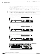
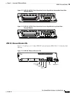
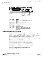
Page 197: ...dule to an RJ 48C Wall Jack IMA Network Module Interface Numbering An individual ungrouped interface on the IMA network module is numbered by interface type and slot and port number for example atm 0 2 An interface that is part of an IMA group loses its individual port number but adopts the IMA group number for example atm 0 ima2 Up to four groups can be created numbered 0 through 3 ATM T1 8ATM EN...

Page 198: ...nal LEDs shown in Figure 12 6 and described in Table 12 1 Figure 12 6 T1 E1 IMA Network Module LEDs Table 12 1 T1 E1 IMA Network Module LEDs LED Color Meaning AL Yellow Alarm indicating loss of signal loss of frame or unavailability because of excessive errors LP Yellow Controller local loopback CD Green Carrier received on telco link ATM T1 8T1 IMA EN 17960 AL LP CD AL LP CD AL T1 IMA 7 T1 IMA 6 ...
Page 199: ...odule see Table 1 6 on page 1 16 HSSI Network Modules The 1 port High Speed Serial Interface HSSI network module see Figure 13 1 provides connectivity for fractional DS3 rate links and slower Figure 13 1 HSSI Network Module Connecting HSSI Modules to the Network The HSSI module contains a 50 pin receptacle color coded blue You can connect this port to a network in either of two ways To an external...

Page 200: ... modem cable See Figure 13 3 Both routers must be at the same site Back to back operation allows you to verify operation of the HSSI port or link routers directly to build a larger node Both routers must be configured to use a 51 84 MHz internal clock Figure 13 2 Connecting the 1 Port HSSI Module to an External DSU EN 11710 HSSI port External DSU HSSI DTE cable HIGH SPEED SERIAL 1HSSI HSSI 0 TD TC...

Page 201: ...he HSSI network module has the additional LEDs shown in Figure 13 4 and described in Table 13 1 Figure 13 4 HSSI Network Module LEDs EN 11711 HIGH SPEED SERIAL 1HSSI HSSI 0 TD TC RD RC LB CN EN 10 100 bTX FAST ETHERNET 1FE COL LINK 100 MBPS FULL DPLX HSSI network module Router INPUT 100 240VAC 50 60HZ 3 0 1 5 AMPS 2E 2W W1 ETHERNET 1 ETHERNET 0 EN AUI WO ACT LNK ACT LNK ACT SERIAL BRI NT1 B1 B2 NT...

Page 202: ... the DSU nor in loopback mode RC Receive Clock Module has detected a receive clock signal During normal operation this signal is received from the external DSU During loopback it is generated internally RD Receive Data Module has detected a receive clock signal During normal operation this signal is received from the external DSU During loopback it is generated internally TC Transmit Clock Module ...

Page 203: ... performance Tip To determine whether your router supports a specific network module see Table 1 6 on page 1 16 Compression Network Modules The compression network module NM COMPR does not provide network interfaces of its own but instead compresses and decompresses data passing through interfaces on other network modules or WAN interface cards in the router See Figure 14 1 Hardware compression is...

Page 204: ...etwork Module LEDs Figure 14 2 shows compression network module LEDs Table 14 1 describes their meaning Figure 14 2 Compression Network Module LEDs Table 14 1 Compression Network Module LEDs LED Meaning EN Green indicates that the module has passed its self tests and is available to the router ERROR Amber indicates that an error was found and if the LED remains on that the error might prevent accu...

Page 205: ...s multipoint network module shown in Figure 15 1 also referred to as a subscriber unit SU provides a high speed broadband fixed wireless radio frequency RF link between each subscriber site and a single headend site This link delivers full duplex data in the licensed MMDS band 2 500 to 2 690 GHz or unlicensed U NII band 5 725 to 5 825 GHz The headend of the system consists of a Cisco uBR7200 serie...

Page 206: ...erters main and diversity Subscriber Unit System Each subscriber unit system see Figure 15 3 consists of the necessary cables and these items A wireless multipoint network module in the router One or two antennas to transmit and receive RF signals to and from the headend Diversity reception of headend transmissions requires two antennas One wireless transverter for each antenna The transverter can...

Page 207: ...ltipoint network modules require an external microcode bundle You can download this microcode at http www cisco com cgi bin tablebuild pl rsu Connecting Wireless Ports to the Network Use an indoor IF coaxial cable to connect the wireless network module Main connector to a power injector If you are using the diversity feature connect the network module Diversity connector to a second power injector...

Page 208: ...ement Instructions Cisco Multipoint Headend Power Feed Panel Replacement Instructions Cisco Multipoint Headend Wireless Transverter Replacement Instructions Cisco Wireless Transverter Hail Shield Installation Instructions CARRIER Indicates the state of the radio link Green means that the radio link is synchronized and the line protocol is up Yellow indicates loss of link synchronization OUT OF SER...

Page 209: ...ule see Table 1 6 on page 1 16 High Density Analog Telephony Network Module The high density analog telephony network module is a modular high density voice network module that provides dual tone multifrequency DTMF detection voice compression and decompression call progress tone generation voice activity detection VAD echo cancellation and adaptive jitter buffering The high density analog telepho...

Page 210: ...witched telephone network PSTN Phones connected to port 8 or port 18 fail over to the PSTN connections through port 14 or port 24 during power outages The digital signal processors DSPs on the card support up to 8 ports of high complexity codecs or up to 16 ports of medium and low complexity codecs The number of DSPs must be increased if more than eight ports of high complexity codecs are needed I...

Page 211: ...female cable from Gray Bar AT125 SM patch panel supports both male and female connection from Gray Bar For ordering information see the Obtaining Technical Assistance section on page xi Figure 16 2 High Density Analog Telephony Card Connected to a Main Distribution Frame Adding DSP Expansion Modules DSP expansion modules can be used if more than eight ports using high complexity codecs are needed ...

Page 212: ... Adding Port Expansion Modules Port expansion modules can be used to increase the number of ports supported on the high density analog telephony network module To install port expansion modules follow these steps Step 1 Decide if the expansion board is going in the EM0 slot or EM1 slot as shown in Figure 16 4 Step 2 Insert the connector on the port expansion module into the module connector on the...

Page 213: ...both mounting screws causes FXO ground start outgoing call operation to fail Step 3 Insert the screws from the hardware kit through the port expansion module into the brackets on the network module Warning Failure to secure the expansion module to the base module with two screws defeats the earth ground causing a potential safety hazard Statement 347 Figure 16 4 Installing a Port Expansion Module ...

Page 214: ... Figure 16 7 shows the RJ 21 connector wiring for the cable used for the high density analog voice card Table 16 4 lists the pinouts The port usage depends on the type of expansion cards installed NM HDA 1 26 Port 1 4 5 14 15 24 Type 4 FXS 62693 Apply label for EM1 here Apply label for EM0 here Table 16 3 High Density Analog Telephony Network Module LEDs LED Meaning EN Green indicates that the mod...

Page 215: ... 2 27 2 1 FXS 3 28 3 2 FXS 4 29 4 3 FXS 5 30 5 4 FXS FXO Expansion board in slot 0 6 31 6 5 FXS FXO 7 32 7 6 FXS FXO 8 33 8 7 FXS FXO 9 34 9 8 FXS Unused 10 35 10 9 FXS Unused 11 36 11 10 FXS Unused 12 37 12 11 FXS Unused 13 38 13 12 Unused Unused 14 39 14 13 Unused FXO failover 15 40 15 14 FXS FXO Expansion board in slot 1 16 41 16 15 FXS FXO 17 42 17 16 FXS FXO 18 43 18 17 FXS FXO 19 44 19 18 FX...

Page 216: ...16 8 Cisco Network Modules Hardware Installation Guide OL 2485 20 Chapter 16 Connecting High Density Analog Telephony Network Modules High Density Analog Voice Card Pinouts ...

Page 217: ...s how to install the 16 and 36 port Ethernet switch network modules The Ethernet switch network module is a modular high density voice network module that provides Layer 2 switching across Ethernet ports The 16 port Ethernet switch network module has 16 10 100BASE TX ports and an optional 10 100 1000BASE T Gigabit Ethernet port The 36 port Ethernet switch network module has 36 10 100BASE TX ports ...

Page 218: ...cur in the VLAN databases and unexpected packet handling may occur Power Considerations The Ethernet switch network module supports inline powering of IP telephones with 48 V power This allows IP phones to be plugged into the standard RJ 45 jack and be powered from this source rather than having a separate plug into an AC wall outlet The Ethernet switch network module requires delivery of 48 V pow...

Page 219: ...signals to indicate status on both internal power supplies Changes on the state of any of these four signals interrupts the main processor on the Cisco 3745 router so software can take the appropriate action Cisco 3725 routers have a single 48 V supply Cisco 3725 routers do not report any power supply status The only software indication of 48 V status is the 48 V status bit provided on the 16 port...

Page 220: ...rough the use of a special tool lock and key or other security means Statement 1072 The Ethernet switch network module is connected to an Ethernet switch or hub with RJ 45 cables See Figure 17 3 RJ 45 cables are not provided with the network module For ordering information see the Obtaining Technical Assistance section on page xi Note When using the NM 16ESW with the MWR 1941 DC router shielded ca...

Page 221: ...Step 3 Insert the connector on the Gigabit Ethernet expansion board into the board connector on the network module Inspect the board to ensure that the board is fully connected See Figure 17 5 for 16 port Ethernet switch network modules or Figure 17 6 for 36 port Ethernet switch network modules Caution Be sure to press firmly on the Gigabit Ethernet expansion board until the board seats correctly ...

Page 222: ...ling a Gigabit Ethernet Expansion Board on a 36 Port Cisco Ethernet Switch Network Module EN NM ESW 16 15x 7x 14x 6x 13x 5x FastEthernet Ports 12x 4x 11x 3x 10x 2x 9x 1x 8x 0x Ext Pwr 48V 0x 8x 7x 15x GE 10 100 1000 Base Tx 62349 75279 NMD ESW 36 FastE th ernet Ports 18x 35x GE1 23x 5x 22x 4x 21x 3x 20x 2x 19x 1x 18x 0x 29x 11x 28x 10x 27x 9x 26x 8x 25x 17 24x 6x 35x 17x 34x 16x 33x 15x 32x 14x 31...

Page 223: ...nsert the connector on the power board into the connector on the network module See Figure 17 8 for 16 port Ethernet switch network modules and Figure 17 9 for 36 port Ethernet switch network modules Note Be sure to press firmly on the power board until the board seats correctly onto the connector Step 5 Insert the screws from the board installation kit through the power board into the standoffs o...

Page 224: ...ng Ethernet Switch Network Modules Adding an Optional Power Board Figure 17 8 Installing a Power Board in a 16 Port Ethernet Switch Network Module EN NM ESW 16 15x 7x 14x 6x 13x 5x FastEthernet Ports 12x 4x 11x 3x 10x 2x 9x 1x 8x 0x Ext Pwr 48V 0x 8x 7x 15x GE 10 100 1000 Base Tx 62350 ...

Page 225: ...er Board Figure 17 9 Installing a Power Board in a 36 Port Ethernet Switch Network Module EN Ext Pwr 48V 0x 8 x GE 10 100 1000 Base Tx 72275 NMD ESW 36 FastE th ernet Ports 18x 35x GE1 23x 5x 22x 4x 21x 3x 20x 2x 19x 1x 18x 0x 29x 11x 28x 10x 27x 9x 26x 8x 25x 17 24x 6x 35x 17x 34x 16x 33x 15x 32x 14x 31x 13x 30x 12x 10 100 1000 Base T x 17x ...

Page 226: ...to the network module Green indicates 48 V power is present on the network module Amber indicates that there is a problem with one or more of the internal or external 48 V power supplies GE Green indicates that the Gigabit Ethernet port is functioning EN Green indicates that the module has passed its self tests and is available to the router EN NM ESW 16 62586 15x 7x 14x 6x 13x 5x FastEthernet Por...

Page 227: ... whether your router supports a specific network module see Table 1 6 on page 1 16 Cisco EtherSwitch Services Modules Cisco EtherSwitch service modules are complete switching platforms and can be stacked with other Cisco switches to form a switching stack integrated with the router and capable of supporting the following features Dynamic addition and removal of individual Cisco EtherSwitch service...

Page 228: ...omply with the Telcordia GR 1089 NEBS standard for electromagnetic compatibility and safety connect the 16 port EtherSwitch service module NME 16ES 1G only to intra building or non exposed wiring or cabling The intrabuilding cable must be shielded and the shield must be grounded at both ends NME 16ES 1G P 16 10 100 Ethernet ports 1 10 100 1000 Ethernet port no StackWise connector ports single wide...

Page 229: ...r use as intra building interfaces only Type 2 or Type 4 ports as described in GR 1089 CORE Issue 4 and require isolation from the exposed OSP cabling The addition of Primary Protectors is not sufficient protection in order to connect these interfaces metallically to OSP wiring Note This module is hereafter referred to as the Cisco StackWise EtherSwitch service module NME XD 48ES 2S P 48 10 100 Et...

Page 230: ...Cisco EtherSwitch service modules see the Cisco Network Modules Hardware Installation Guide at the following URL http www cisco com en US products hw modules ps2797 products_module_installation_guide_b ook09186a00802d2910 html Table 18 1 shows the Cisco router platforms that support the Cisco EtherSwitch service modules 16 Port Cisco EtherSwitch Service Module Figure 18 1 shows the 16 port Cisco E...

Page 231: ...ibes the port types and port numbering on the service modules Port Types Port Numbering 121360 GE 1 15x 16x 2x 16x EN 13x 14x 11x 12x 9x 10x 7x 8x 5x 6x 3x 4x 1x 2x NME 16ES 1G P 121361 NME X 23ES 1G P 24x 23x 22x 21x 20x 19x 18x 17x 16x 15x 14x 13x 12x 11x 10x 9x 8x 7x 6x 5x 4x 3x 2x 2x 24x EN GE 1 121362 24x SYST MASTR STAT DUPLX SPEED STACK PoE MODE STACK 1 STACK 2 EN LASERPRODUKT DER KLASSE 1 ...

Page 232: ...ombination of half duplex full duplex 10 Mbps or 100 Mbps You can set the 10 100 1000 ports to operate at 10 Mbps 100 Mbps or 1000 Mbps in full duplex You can also set these ports for speed and duplex autonegotiation in compliance with IEEE 802 3ab The default setting is autonegotiate When set for autonegotiation the port senses the speed and duplex settings of the attached device and advertises i...

Page 233: ...ules Hardware Installation Guide at the following URL http www cisco com en US products hw modules ps2797 products_module_installation_guide_book 09186a00802d2910 html Table 18 2 Port Speed and Duplex Port Function Explanation Speed The operating speed of the switch port You can choose Auto autonegotiation if the connected device can negotiate the link speed with the switch port The default settin...

Page 234: ...itch config interface fa1 0 3 Cisco EtherSwitch Service Module LEDs Cisco EtherSwitch service module LEDs provide green amber and off states for system and port status The following sections describe LEDs on the service modules EN LED System LED Master LED Port Mode LEDs Port LEDs Port LEDs in Stack Mode Note LEDs for System Master Port Mode and PoE are available on the 24 port Cisco StackWise Eth...

Page 235: ...nings Table 18 3 EN LED Color System Status Off The Cisco EtherSwitch service module is not yet operational Green The Cisco EtherSwitch service module is operational Amber A stack error has occurred Table 18 4 System SYST LED LED Color Description Off Module POST is not in progress Green Module POST is in progress Amber System is receiving power but is not functioning properly 121531 24x SYST MAST...

Page 236: ...isco StackWise EtherSwitch service module was electing the stack master or a stack error occurred Table 18 6 Mode LEDs LED Mode Description STAT Port status The port status In this mode the LED shows link status and link activity This is the default mode DUPLX Port duplex mode The port duplex mode full duplex or half duplex SPEED Port speed The port operating speed 10 100 or 1000 Mbps STACK Stack ...

Page 237: ...rror frames can affect connectivity and errors such as excessive collisions Cyclic Redundancy Check CRC errors and alignment and jabber errors are monitored for a link fault Amber The port is blocked by the Spanning Tree Protocol STP and is not forwarding data Note After a port is reconfigured the port LED can remain amber for up to 30 seconds while STP checks the Cisco StackWise EtherSwitch servi...

Page 238: ... power or at least one of the 10 100 or 10 100 1000 ports has a PoE fault Table 18 8 Port LED on the Cisco EtherSwitch Service Modules Excluding the Cisco StackWise EtherSwitch Service Module Port LED Color Description Off No link or the port was administratively shut down On PoE ports no inline powered device PD detected or the port is not connected Green A link is present The port or system is f...

Page 239: ... authorized within the restricted access location are made aware of the hazard A restricted access area can be accessed only through the use of a special tool lock and key or other means of security Statement 1072 Power Considerations for the Router Cisco 2800 series Cisco 3700 series and Cisco 3800 series routers supply 48 V power internally with AC IP power supplies to the Cisco EtherSwitch serv...

Page 240: ...ing guidelines before you power the Cisco EtherSwitch service modules in a stack The sequence in which the Cisco EtherSwitch service modules are initially powered up might affect the Cisco EtherSwitch service module that becomes the stack master If you want a particular Cisco EtherSwitch service module to become the stack master power up that Cisco EtherSwitch service module first This Cisco Ether...

Page 241: ...there is access to the front of the rack if you are planning to stack the Cisco EtherSwitch service modules For concepts and procedures to manage Cisco EtherSwitch service module stacks see the Catalyst 3750 Switch Software Configuration Guide Cisco IOS Release 12 2 at the following URL http www cisco com univercd cc td doc product lan cat3750 index htm See these sections for additional considerat...

Page 242: ...o EtherSwitch service module 1 becomes the stack master of one stack and one of the Catalyst 3750 switches becomes the stack master of the second stack 121915 A ACT FE 0 1 PVDM2 PVDM1 PVDM0 AIM1 AIM0 FE 0 0 S SPEED A FDX A LINK A F S L A F S L 24x SYST MASTR STAT DUPLX SPEED STACK LINE PWR MODE EN LASERPRODUKT DER KLASSE 1 1 PRODUCTO LASER CLASE 1 PRODUIT LASER DE CLASSE 1 CLASS 1 LASER PRODUCT AR...

Page 243: ...AIM0 FE 0 0 S SPEED A FDX A LINK A F S L A F S L 24x SYST MASTR STAT DUPLX SPEED STACK LINE PWR MODE EN LASERPRODUKT DER KLASSE 1 1 PRODUCTO LASER CLASE 1 PRODUIT LASER DE CLASSE 1 CLASS 1 LASER PRODUCT ARE ON THE FACEPLATE BE SECURED ALL 6 32 THUMB SCREWS MUST WHILE HULC STACK CABLES GE 1 2x 2x 1x 4x 3x 6x 5x 8x 7x 11x 9x 12x 14x 13x 16x 15x 18x 17x 20x 19x 22x 21x 24x 23x 10x A C B NME XD 24ES 1...

Page 244: ...ervice module and secure the screws tightly See Figure 18 13 Figure 18 13 Securing the Cisco StackWise Cable STACK 1 ST LASERPRODUKT DER KLASSE 1 1 PRODUCTO LASER CLASE 1 PRODUIT LASER DE CLASSE 1 CLASS 1 LASER PRODUCT ARE ON THE FACEPLATE BE SECURED ALL 6 32 THUMB SCREWS MUST WHILE HULC STACK CABLES GE 1 2x 122215 STACK 1 ST LASERPRODUKT DER KLASSE 1 1 PRODUCTO LASER CLASE 1 PRODUIT LASER DE CLAS...

Page 245: ...le NM CE BP 40G K9 see Figure 19 1 CE network module with a 80 GB Disk Expansion Module NM CE BP 80G K9 see Figure 19 1 CE network module with a SCSI Controller Expansion Module and a 68 pin SCSI connector for connection to an external storage array NM CE BP SCSI K9 see Figure 19 2 The 80 GB CE network module can run Application and Content Networking System ACNS software or Cisco Wide Area File S...

Page 246: ... has been turned off or the network module has been removed from the router the real time clock stops Figure 19 1 Faceplate for the CE Network Module with 40 or 80 GB Disk Expansion Module Figure 19 2 Faceplate for the CE Network Module with SCSI Connector Expansion Module Note Some early CE network modules have an inactive USB port on the faceplate This USB port has been removed in later Cisco CE...

Page 247: ... external Cisco storage array to the CE network module before powering on the router or network module To connect a CE network module with a SCSI controller expansion module to an external storage array use a 68 pin low voltage differential LVD SCSI cable Connect the cable to the SCSI port on the network module to the SCSI port on the external Cisco storage array See Figure 19 4 Cisco Storage Arra...

Page 248: ...s self tests and is available to the router CE network modules also display an additional power PWR LED and a CompactFlash CF LED on the faceplate and two additional LEDs for the Fast Ethernet port See Figure 19 5 and Table 19 1 Figure 19 5 CE Network Module LEDs NM CE BP EN PWR FastEthernet 0 DISK LINK ACT CF 72351 VHDCI connector on I O module Table 19 1 Content Engine Network Modules for Cachin...

Page 249: ...u remove a network module install another module exactly like it in its place If you remove a 2 slot network module along with any installed WAN or voice interface cards install another module and card combination exactly like it For a description of informational and error messages that may appear on the console during this procedure see the hardware installation guide for your type of router To ...

Page 250: ... chassis slot Step 9 Slide the CE network module out of the slot Step 10 Align the replacement CE network module with the guides in the chassis slot and slide it gently into the slot Note If the router is not fully configured with network modules make sure that blank panels fill the unoccupied chassis slots to provide proper airflow Step 11 Push the module into place until you feel its edge connec...

Page 251: ...tation see the Obtaining Documentation section on page viii For information on obtaining technical assistance see the Obtaining Technical Assistance section on page xi Hardware Documentation For information on installing and removing CE network module expansion modules see the Installing Expansion Modules on Cisco CE Network Modules for Caching and Content Delivery document Cisco IOS Software Docu...

Page 252: ...19 8 Cisco Network Modules Hardware Installation Guide OL 2485 20 Chapter 19 Connecting Content Engine Network Modules for Caching and Content Delivery Related Documents ...

Page 253: ...rk module see Table 1 6 on page 1 16 1 Port T3 E3 Network Modules The NM 1T3 E3 network module is a single port universal T3 E3 network module with integrated CSU DSU clear channel and subrate support See Figure 20 1 Channels on the network module can be configured as either T3 or E3 through Cisco IOS software Figure 20 1 1 Port T3 E3 Network Module Faceplate Note The NM 1T3 E3 network module prov...

Page 254: ...e of public network can cause severe injury or damage your router Statement 1031 Caution To minimize transient surges the internal wiring should not be routed in the same conduit with power lines or external telephone lines Figure 20 2 Connecting a T3 E3 Network Module to a Networking Device Cisco 7603 Router Shown 72715 SUPERVISOR2 WS X6K SUP2 2GE STATUS SYSTEM CO NSO LE PW R M G M T RESET CONSOL...

Page 255: ...ocuments For additional information see the following documents Tip For information on obtaining documentation see the Obtaining Documentation section on page viii For information on obtaining technical assistance see the Obtaining Technical Assistance section on page xi Table 20 1 T3 E3 Network Module LEDs LED Meaning CD Green indicates that a signal is present on the port LP Yellow indicates tha...

Page 256: ...485 20 Chapter 20 Connecting T3 E3 Network Modules Related Documents Cisco IOS Software Documentation For information on Cisco IOS software features specific to the T3 E3 network module see the Clear Channel T3 E3 Network Module with Integrated CSU DSU document ...

Page 257: ...e whether your router supports a specific network module see Table 1 6 on page 1 16 Gigabit Ethernet Network Modules The Gigabit Ethernet network module provides single port Gigabit Ethernet connectivity through an installed Gigabit interface converter GBIC The GBIC determines the type of connectivity available to the network module See Figure 21 1 Figure 21 1 Gigabit Ethernet Network Module Facep...

Page 258: ...n 25 km 15 5 miles Install the attenuators between the male SC connector on the cable and the female SC connector on the network module GBIC LX LH Long wavelength or long haul 1000BASE LX LH 10 micron SMF cable yellow with SC connectors1 Tip If using an MMF cable install a mode conditioning patch cord CAB GELX 625 GBIC SX Short wavelength 1000BASE SX 62 5 micron MMF cable orange with SC connectors...

Page 259: ... Access Routers before connecting the network module to the network Laser Safety Guidelines Optical GBICs use a small laser to generate the fiber optic signal Keep the transmit port covered whenever a cable is not connected to the port The module faceplate carries a Class 1 laser warning label See Figure 21 3 Figure 21 3 Class 1 Laser Warning Label Warning Because invisible laser radiation may be ...

Page 260: ... Figure 21 4 Figure 21 4 Connecting a Gigabit Ethernet Network Module to a Cisco 7200 Series Router Gigabit Ethernet Network Module LEDs All network modules have an enable EN LED This LED indicates that the module has passed its self tests and is available to the router See Figure 21 5 and Table 21 2 for LEDs specific to the Gigabit Ethernet network module 72706 ETHERNET 10BT EN AB LE D 0 2 1 3 LI...

Page 261: ...ion on page xi CWDM Passive Optical System Documentation For more information on the CWDM Passive Optical System which is often used with CWDM GBICs see the Cisco 1000BASE CWDM Series Passive Optical System Installation Note document Table 21 2 Gigabit Ethernet Network Module LEDs LED Meaning LINK Green indicates that a link has been established between the network module and another networking de...

Page 262: ...21 6 Cisco Network Modules Hardware Installation Guide OL 2485 20 Chapter 21 Connecting Gigabit Ethernet Network Modules Related Documents ...

Page 263: ...ocuments page 22 4 Tip To determine whether your router supports a specific network module see Table 1 6 on page 1 16 CIDS Network Modules This section provides information on the CIDS network module NM CIDS K9 see Figure 22 1 Caution To comply with the Telcordia GR 1089 NEBS standard for electromagnetic compatibility and safety connect the CIDS network module NM CIDS K9 only to intrabuilding or n...

Page 264: ...Telcordia GR 1089 NEBS standard for electromagnetic compatibility and safety connect the CIDS network module NM CIDS K9 only to intrabuilding or nonexposed wiring or cabling The intrabuilding cable must be shielded and the shield must be grounded at both ends Figure 22 2 Connecting a CIDS Network Module to a Fast Ethernet Hub CIDS Network Module LEDs All network modules have an enable EN LED This ...

Page 265: ...erly fashion before the network module is removed Caution Cisco routers support OIR with similar modules only If you remove a network module install another module exactly like it in its place If you remove a two slot network module along with any installed WAN or voice interface cards install another module and card combination exactly like it For a description of informational and error messages...

Page 266: ...onfigured with network modules make sure that blank panels fill the unoccupied chassis slots to provide proper airflow Step 6 Push the module into place until you feel its edge connector mate securely with the connector on the backplane Step 7 Reconnect the network interface cable previously removed in Step 2 Step 8 Tighten the two captive screws on the faceplate Step 9 Reset the CIDS network modu...

Page 267: ...tall and initially configure Cisco IDS components see the Quick Start Guide for the Cisco Intrusion Detection System Version 4 1 For installation instructions for all Cisco IDS version 4 1 hardware components including appliances modules accessories and upgrades such as the IDS XL card and basic configuration tasks using command line interface CLI see the Cisco Intrusion Detection System Appliance...

Page 268: ...22 6 Cisco Network Modules Hardware Installation Guide OL 2485 20 Chapter 22 Connecting Cisco Intrusion Detection System Network Modules Related Documents ...

Page 269: ...r router supports a specific network module see Table 1 6 on page 1 16 Cisco Unity Express Network Module Overview This section provides information on the Cisco Unity Express network module NM CUE See Figure 23 1 Caution To comply with the Telcordia GR 1089 NEBS standard for electromagnetic compatibility and safety connect the Cisco Unity Express network module NM CUE only to intrabuilding or non...

Page 270: ...d Fast Ethernet port LEDs are not used by the Cisco Unity Express network module Figure 23 2 NM CUE LEDs 88734 NM CUE EN PWR FastEthernet 0 DISK LINK ACT NOT SUPPORTED CF Table 23 1 Cisco Unity Express Network Module LEDs LED Meaning ACT There is activity on the Fast Ethernet connection Note This LED is not used on the NM CUE CF The compact Flash module is active Note This LED is not used on the N...

Page 271: ...only If you remove a network module install another module exactly like it in its place For a description of informational and error messages that may appear on the console during this procedure see the hardware installation guide for your type of router To perform online removal of a Cisco Unity Express network module and insertion of a replacement follow these steps with the router in privileged...

Page 272: ... proper airflow Step 9 Push the module into place until you feel its edge connector mate securely with the connector on the backplane Step 10 Tighten the two captive screws on the module faceplate Step 11 Check that the network module LEDs come on and that the power and enable LEDs on the front panel have also come on This inspection ensures that connections are secure and that the new unit is ope...

Page 273: ...n obtaining documentation see the Obtaining Documentation section on page viii For a list of orderable documentation search the Cisco Price List under Documentation Cisco Unity Express Software Documentation For end user information on Cisco Unity Express software see the Cisco Unity Express End User Card For system admininstrator information on the Cisco Unity Express software see the Cisco Unity...

Page 274: ...23 6 Cisco Network Modules Hardware Installation Guide OL 2485 20 Chapter 23 Connecting Cisco Unity Express Network Modules Related Documents ...

Page 275: ... page 1 16 Cisco Unity Express Enhanced Network Modules The Cisco Unity Express enhanced network module NME CUE provides 24 ports that store a maximum of 250 voice mailboxes and 300 hours of voice messages See Figure 24 1 Caution To comply with the Telcordia GR 1089 NEBS standard for electromagnetic compatibility and safety connect the Cisco Unity Express enhanced network module NME CUE only to in...

Page 276: ...than 4 seconds to cause an immediate module shutdown which may impact file operations that are in progress DISK Status of hard drive activity On Active Off Inactive SYS Status of system shutdown Note Do not remove power without first shutting down the application On Application is stable Off System is shut down and ready for host power down Flashing System shutdown is in progress EN Status of the ...

Page 277: ... network users maintains routing information and ensures session preservation Caution Unlike other network modules Cisco Unity Express enhanced network modules use hard disks Online removal of disks without proper shutdown can cause file system corruption and might render the disk unusable You must shut down the operating system on the network module in an orderly way before removing or powering d...

Page 278: ...odule integrated service engine slot unit shutdown Step 6 Shut down the network module interface Router config interface integrated service engine slot unit Router config if shutdown Router config if exit Step 7 Unplug all network interface cables from the network module Step 8 Loosen the two captive screws that are holding the network module in the chassis slot Step 9 Slide the network module out...

Page 279: ...tep 15 Restore the network module running configuration by using the following command from the service module prompt Se copy tftp running config tftp server address filename Step 16 Exit the network module session by pressing Control Shift 6 followed by pressing x Step 17 On the router clear the network module session by using the following command Router service module integrated service engine ...

Page 280: ...tration configuration and operation Cisco Unity Express at http www cisco com en US products sw voicesw ps5520 tsd_products_suppo rt_series_home html Cisco IOS software website and reference documentation Cisco IOS Software at http www cisco com en US products sw iosswrel tsd_products_support_cate gory_home html Technical documentation including feedback and assistance What s New in Cisco Product ...

Page 281: ...ntegrated services routers Tip To determine whether your router supports a specific network module see Table 1 6 on page 1 16 Network Analysis Module Overview This section provides information on the network analysis module NM NAM See Figure 25 1 All network modules have an enable EN LED This LED indicates that the module has passed its self tests and is available to the router All network analysi...

Page 282: ...ompatibility and safety connect the network analysis module NM NAM only to intrabuilding or nonexposed wiring or cabling The intrabuilding cable must be shielded and the shield must be grounded at both ends Note RJ 45 cables are not available from Cisco Systems These cables are widely available and must be Category 5 cables Table 25 1 Cisco Network Analysis Module NM NAM LEDs Callout LED Meaning 1...

Page 283: ...similar modules only If you remove a network module install another module exactly like it in its place If you remove a two slot network module along with any installed WAN or voice interface cards install another module and card combination exactly like it For a description of informational and error messages that may appear on the console during this procedure see the hardware installation guide...

Page 284: ...oved in Step 3 Step 9 Tighten the two captive screws on the faceplate Step 10 Reset the network analysis module using the reset command Router service module analysis module slot 0 reset Use reset only to recover from shutdown or failed state Warning May lose date on the hard disc Do you want to reset confirm Step 11 Press Enter to confirm the request The network analysis module resets itself Step...

Page 285: ...onal References page 26 5 Tip To determine whether your Cisco router supports a specific network module see Table 1 6 on page 1 16 NAM Enhanced Network Modules The NAM enhanced network module NME NAM 80S monitors and analyzes network traffic using remote monitoring RMON RMON extensions for switched networks SMON and other management information bases MIBs See Figure 26 1 on page 26 2 The NAM enhan...

Page 286: ...hernet link On Link is enabled Off Link is disabled ACT Status of Gigabit Ethernet activity On Active Off Inactive DISK Status of hard drive activity On Active Off Inactive SYS Status of system shutdown Note Do not remove power without first shutting down the application On Application is stable Off System is shut down and ready for host power down Flashing System shutdown is in progress EN Status...

Page 287: ...faces that connect to the OSP or its wiring These interfaces are designed for use as intra building interfaces only Type 2 or Type 4 ports as described in GR 1089 CORE Issue 4 and require isolation from the exposed OSP cabling The addition of Primary Protectors is not sufficient protection in order to connect these interfaces metallically to OSP wiring To connect NAM enhanced network modules to an...

Page 288: ...nsole session using the following command Router service module integrated service engine slot unit session clear Step 5 Perform a graceful shutdown of the network module disk drive by using the following command Router service module integrated service engine slot unit shutdown Step 6 Shut down the network module interface Router config interface integrated service engine slot unit Router config ...

Page 289: ...session clear Additional References For additional information see the following documents and resources Related Topic Document Title NAM software installation and administration configuration and operation Cisco Branch Router Series NME NAM Installation and Configuration Note at http www cisco com en US products sw cscowork ps5401 products_installati on_and_configuration_guide09186a00807ee90a htm...

Page 290: ...26 6 Cisco Network Modules Hardware Installation Guide OL 2485 20 Chapter 26 Connecting NAM Enhanced Network Modules Additional References ...

Page 291: ...rt T1 E1 RJ 48 Interface Network Modules NM CEM 4TE1 to the Network page 27 9 Tip To determine whether your router supports a specific network module see Table 1 6 on page 1 16 Cisco CEoIP Network Modules Cisco CEoIP network modules provide a virtual circuit through an IP network similar to a leased line Transport of data regardless of the content or structure of the data stream is entirely transp...

Page 292: ...standard for electromagnetic compatibility and safety connect the 4 port serial interface network module NM CEM 4SER only to intrabuilding or nonexposed wiring or cabling The intrabuilding cable must be shielded and the shield must be grounded at both ends The interface type provided by the port is determined by the cable connected to the port For information on interface specific cabling requirem...

Page 293: ...089 NEBS standard for electromagnetic compatibility and safety connect the 4 port serial interface network module NM CEM 4SER only to intrabuilding or nonexposed wiring or cabling The intrabuilding cable must be shielded and the shield must be grounded at both ends The following basic set of control signals is used on Cisco 12 in 1 cables Data Terminal Ready DTR Data Set Ready DSR Request to Send ...

Page 294: ...on on using Cisco 12 in 1 cables with the 4 port serial interface network module see Table 27 3 Figure 27 4 illustrates how to connect the Cisco 12 in 1 cable to the network module For information on using Cisco Extended 12 in 1 cables with the 4 port serial interface network module see Table 27 4 Figure 27 5 illustrates how to connect the Cisco Extended 12 in 1 cable to the network module All ser...

Page 295: ...or DCE mode appropriate for your network Figure 27 4 illustrates how to connect the Cisco 12 in 1 cable to the network module 9600 50 15 1025 312 19200 25 8 500 150 38400 12 4 250 75 56000 9 3 100 30 Table 27 2 Maximum Recommended Speeds and Distances for Each Serial Interface Type continued EIA TIA 232 Distance EIA TIA 449 530 530A V 35 X 21 Distance Data Rate bps Feet Meters Feet Meters Table 27...

Page 296: ...al Interface Network Module NM CEM 4SER Table 27 4 lists the Cisco Extended 12 in 1 interface cables supported by the 4 port serial interface network module Use the cable part number to order replacement or spare cables for the interface and DTE or DCE mode appropriate for your network Figure 27 5 illustrates how to connect the Cisco 12 in 1 cable to the network module AL EN NM CEM 4SER See Manual...

Page 297: ...ended 12 in 1 Interface Cable Part Numbers Used with the 4 Port Serial Interface Network Module NM CEM 4SER Interface DCE DTE Cisco Cable Part Number EIA TIA 232 Female DCE Male DTE CAB SS 232FC EXT CAB SS 232MT EXT EIA TIA 449 Female DCE Male DTE CAB SS 449FC EXT CAB SS 449MT EXT EIA 530 Female DCE Male DTE CAB SS 530FC EXT CAB SS 530MT EXT EIA 530A Female DCE Male DTE CAB SS 530AFC EXT CAB SS 53...

Page 298: ... Network Modules to the Network Figure 27 5 Connecting the Cisco Extended 12 in 1 Interface Cable to the 4 Port Serial Interface Network Module NM CEM 4SER AL EN NM CEM 4SER See Manual before installation Connectors for Extended Control Signals CEM 3 CEM 1 CEM 2 CEM 0 ACT LP LP ACT 88923 EIA TIA 449 V 35 Connections at the CPE EIA TIA 232 EIA TIA 530 EIA TIA 530A ...

Page 299: ...8 interface network module NM CEM 4TE1 uses a RJ 48 straight through cable to connect to the customer premises equipment CPE for use in T1 or E1 circuit emulation See Figure 27 7 Note All four ports on the network module must operate in the same software configured mode either as T1 ports or as E1 ports The NM CEM 4TE1 network module does not support combinations of T1 and E1 ports on the same net...

Page 300: ...EM 4TE1 network module provides four 120 ohm balanced ports To connect any of these ports to a 75 ohm unbalanced network use Cisco cable CAB ADP 75 120 For more information see the Installing the 75 120 Ohm Adapter Cable on E1 Multichannel Port Adapters document Figure 27 7 Connecting the 4 Port T1 E1 RJ 48 Interface Network Module NM CEM 4TE1 to the Network AL EN NM CEM 4TE1 T1 E1 3 T1 E1 2 T1 E1...

Page 301: ...n module for voice and fax is available as an 8 port analog voice module EVM HD 8FXS DID Each port can be configured in Foreign Exchange Station FXS or Direct Inward Dialing DID mode through Cisco IOS software commands Note FXS supports on premises applications only Cisco high density extension modules provide an integrated high density analog and digital voice interface for small or medium branch...

Page 302: ...d wiring or cabling The intrabuilding cable must be shielded and the shield must be grounded at both ends Cisco High Density Extension Module LEDs and Interfaces Figure 28 1 shows high density extension module LEDs and interfaces Figure 28 1 Cisco High Density Extension Module EVM HD 8FXS DID LEDs 1 EM0 Green indicates presence of an installed expansion module in slot EM0 3 EN Green indicates that...

Page 303: ...h port port 5 provides a trunk bypass TBP or power failover capability The 8 port analog voice fax expansion module EM HDA 8FXS adds an additional eight FXS ports to the Cisco high density extension module Tip When router power is off connect an analog phone to the FXO line to make a call See the Connecting Cisco High Density Extension Modules to the Network section on page 28 6 for more informati...

Page 304: ...on the underside of the expansion module with the connectors for the slot you plan to use on the network module See Figure 28 2 Step 3 Using gentle pressure insert the connectors on the underside of the expansion module into the connectors on the network module Tip Use the alignment pins on the network module brackets to guide the expansion module during installation Note Press firmly on the expan...

Page 305: ...twork module Warning Failure to secure the expansion module to the base module with two screws defeats the earth ground causing a potential safety hazard Statement 347 Tip To maintain proper seating of the network module tighten the rear screw first Step 6 Apply the appropriate label on the front of the network module faceplate See Figure 28 3 1 Expansion module connector on the network module for...

Page 306: ...l with an RJ 21 cable See Figure 28 4 RJ 21 cables are not provided with the network module Warning Do not work on the system or connect or disconnect cables during periods of lightning activity Statement 1001 Caution To comply with the Telcordia GR 1089 NEBS standard for electromagnetic compatibility and safety connect the 8 port analog voice fax expansion module EM HDA 8FXS and 4 port digital vo...

Page 307: ... Black Box Corporation JPM2194A see Figure 28 5 Mention of products or services other than Cisco products or services is for information purposes only and constitutes neither an endorsement nor a recommendation The Black Box patch panel accommodates RJ 11 and RJ 45 combinations possible on Cisco high density expansion modules and offers flexibility for expansion module upgrades either analog or di...

Page 308: ... FXO ports on an FXS or FXO expansion module when installed in slot EM1 Note Applies to EM HDA 8FXS EM HDA 6FXO or EM HDA 3FXS 4FXO expansion modules only 3 RJ 11 receptacles for FXS or FXO ports on an FXS or FXO expansion module when installed in slot EM0 Note Applies to EM HDA 8FXS EM HDA 6FXO or EM HDA 3FXS 4FXO expansion modules only 6 RJ 45 receptacles for BRI ports on the EM 4BRI NT TE when ...

Page 309: ...5 or port 23 until the router is powered down Caution Analog phones connected to the power fail ports should not be connected in parallel to a normal FXS port on Cisco high density extension modules The protection circuit on the FXS port can interfere with phone operation when router power is off Cisco High Density Extension Module Cable Pinouts Figure 28 6 shows the RJ 21 connector wiring for the...

Page 310: ...Tip FXS Port 8 Tip Port 8 Tip Port x 0 SX 9 Port 8 Ring FXS Port 8 Ring Port 8 Ring Port x 0 SX 35 Port 9 Tip FXS Port 9 Tip Port 9 Tip Port x 0 SR 10 Port 9 Ring FXS Port 9 Ring Port 9 Ring Port x 0 SR 36 Port 10 Tip FXS Port 10 Tip Port 10 Tip Port x 1 SX 11 Port 10 Ring FXS Port 10 Ring Port 10 Ring Port x 1 SX 37 Port 11 Tip Unused Port 11 Tip Port x 1 SR 12 Port 11 Ring Unused Port 11 Ring Po...

Page 311: ...ort 19 Ring Port x 5 SR 46 Port 20 Tip FXO Port 20 Tip Port 20 Tip Port x 6 SX 21 Port 20 Ring FXO Port 20 Ring Port 20 Ring Port x 6 SX 47 Port 21 Tip FXO Port 21 Tip Port 21 Tip Port x 6 SR 22 Port 21 Ring FXO Port 21 Ring Port 21 Ring Port x 6 SR 48 Port 22 Tip FXO Port 22 Tip Unused Port x 7 SX 23 Port 22 Ring FXO Port 22 Ring Unused Port x 7 SX 49 Port 23 Tip FXO Port 23 Tip PFP Tip Port x 7 ...

Page 312: ...28 12 Cisco Network Modules Hardware Installation Guide OL 2485 20 Chapter 28 Connecting Cisco High Density Extension Modules Cisco High Density Extension Module Cable Pinouts ...

Page 313: ...AIC network module can be connected to a patch panel The patch panel provides the bias to the circuit The analog alarm inputs can be configured to monitor either DC voltage or current The AIC can measure voltage from 60 to 60 V or current from 0 to 20 mA The control relay can be operated to turn an external device on or off When an event is detected notification messages are sent to the Operations...

Page 314: ...for monitoring voltage Make sure that your alarms are connected to the proper sensors Caution Connect the cable to the AIC before connecting it to the patch panel or other connection Otherwise voltage could be present on the male pins that connect to the AIC Caution The signal I O connections on this unit are intended only for connection to NEC CEC Class 2 or equivalent circuit This means that the...

Page 315: ...work Module Faceplate Connections Figure 29 4 AIC Network Module Connected to AIC 1 Patch Panel Cisco 2611 router W1 Patch panel AIC1 C1 C2 C3 C4 C1 C2 C3 C4 Cables to main distribution frame 58747 37423 Transition cable Patch panel EN AIC 64 CONN 2 STAT CONN 4 CONN 1 CONN 3 Micro DB 50 connectors SEE MANUAL BEFORE INSTALLATION SERIAL 1 SERIAL 0 CONN CONN WIC 2A S SEE MANUAL BEFORE INSTALLATION SE...

Page 316: ...anel Connected to MDF SEE MANUAL BEFORE INSTALLATION SERIAL 1 SERIAL 0 CONN CONN WIC 2A S SEE MANUAL BEFORE INSTALLATION SERIAL 1 SERIAL 0 CONN CONN WIC 2T Cisco 2611 100 240V 1A 50 60 Hz 47 W W0 AUX CONSOLE W1 ETHERNET 1 ETHERNET 0 LINK LINK ACT ACT 58710 CONN 1 CONN 2 CONN 3 CONN 4 AIC 2 CONN 1 CONN 2 CONN 3 CONN 4 AIC 1 58711 POWER RPS ACTIVITY Cisco 2600SERIES Cables to main distribution frame...

Page 317: ...ontrol N O 7 8 Alarm Neg 8 Alarm Neg 33 See Table 29 2 Control Common 8 33 Alarm Pos 8 Alarm Pos 33 See Table 29 2 Control N O 8 9 Alarm Neg 9 Alarm Neg 34 See Table 29 2 Control Common 9 34 Alarm Pos 9 Alarm Pos 34 See Table 29 2 Control N O 9 10 Alarm Neg 10 Alarm Neg 35 See Table 29 2 Control Common 10 35 Alarm Pos 10 Alarm Pos 35 See Table 29 2 Control N O 10 11 Alarm Neg 11 Alarm Neg 36 See T...

Page 318: ...g 23 Alarm Neg 48 Not used Not used 48 Alarm Pos 23 Alarm Pos 48 Not used Not used 24 Alarm Neg 24 Alarm Neg 49 Not used Not used 49 Alarm Pos 24 Alarm Pos 49 Not used Not used 25 Alarm Neg 25 Alarm Neg 50 Not used Not used 50 Alarm Pos 25 Alarm Pos 50 Not used Not used Table 29 2 Voltage Monitor Connections on Connector 3 for the AIC 1 Patch Panel Terminal Strip Signal 1 RET Alarm Pos 57 BAT Alar...

Page 319: ...arm Pos 57 Control N O 7 8 Alarm Neg 8 Alarm Neg 33 Alarm Neg 58 Control Common 8 33 Alarm Pos 8 Alarm Pos 33 Alarm Pos 58 Control N O 8 9 Alarm Neg 9 Alarm Neg 34 Alarm Neg 59 Control Common 9 34 Alarm Pos 9 Alarm Pos 34 Alarm Pos 59 Control N O 9 10 Alarm Neg 10 Alarm Neg 35 Alarm Neg 60 Control Common 10 35 Alarm Pos 10 Alarm Pos 35 Alarm Pos 60 Control N O 10 11 Alarm Neg 11 Alarm Neg 36 Alarm...

Page 320: ... software encounters any other fatal fault in its firmware during normal operation Table 29 4 defines the state of the card with respect to the states of the LEDs Figure 29 7 AIC Network Module LEDs 19 Alarm Neg 19 Alarm Neg 44 Not used Not used 44 Alarm Pos 19 Alarm Pos 44 Not used Not used 20 Alarm Neg 20 Alarm Neg 45 Not used Not used 45 Alarm Pos 20 Alarm Pos 45 Not used Not used 21 Alarm Neg ...

Page 321: ...r 29 Connecting Alarm Interface Controller Network Modules AIC Network Module LEDs Table 29 4 AIC LED Description EN LED STAT LED Description Green Orange Off Off Off No power to the AIC On Off Off Software initializing On On Off Normal operation On Off On Fault encountered ...

Page 322: ...29 10 Cisco Network Modules Hardware Installation Guide OL 2485 20 Chapter 29 Connecting Alarm Interface Controller Network Modules AIC Network Module LEDs ...

Page 323: ...r Cisco router supports a specific network module see Table 1 6 on page 1 16 Cisco AON Network Modules The Cisco AON network modules provide application level intelligence improved message visibility and security and reduced total cost of ownership by consolidating elements of network and application infrastructures Two models of Cisco AON network modules are available NM AON K9 See Figure 30 1 on...

Page 324: ...gabit Ethernet link On Link is enabled Off Link is disabled ACT Status of Gigabit Ethernet activity On Active Off Inactive PWR SYS Status of system shutdown Note Do not remove power without first shutting down the application On Application is stable Off System is shut down and ready for host power down Flashing System shutdown is in progress 170346 SHUTDOWN GRACEFUL 1 s IMMEDIATE 4 s CF LINK ACT ...

Page 325: ...sted pair UTP cable and connect the RJ 45 Gigabit Ethernet port on the network module to a switch hub repeater server or other Gigabit Ethernet network device Warning To comply with the Telcordia GR 1089 NEBS standard for electromagnetic compatibility and safety connect the NME AON K9 network module only to intra building or unexposed wiring or cable The intrabuilding cable must be shielded and th...

Page 326: ...onboard Ethernet ports and network module slots are not supported For details about configuring HIMI connections see the Cisco High Speed Intrachassis Module Interconnect HIMI Configuration Guide on Cisco com http www cisco com en US products ps5855 prod_configuration_guide09186a008068ea83 html Online Insertion and Removal of Cisco Network Modules Some Cisco access routers allow you to replace net...

Page 327: ...grated service engine slot unit shutdown Step 6 Shut down the network module interface Router config interface integrated service engine slot unit Router config if shutdown Router config if exit Step 7 Unplug all network interface cables from the network module Step 8 Loosen the two captive screws holding the network module in the chassis slot Step 9 Slide the network module out of the slot Step 1...

Page 328: ...p 15 Restore the network module running configuration by using the following command from the service module prompt Router copy tftp running config tftp server address filename Step 16 Exit the network module session by pressing Control Shift 6 followed by x Step 17 On the router clear the network module session by using the following command Router service module integrated service engine slot un...

Page 329: ...nd Administration Guide http www cisco com univercd cc td doc product aon aonadmin pdf Cisco Application Oriented Networking Development Studio User Guide http www cisco com univercd cc td doc product aon ads index htm Cisco IOS software website and reference documentation Cisco IOS Software http www cisco com en US products sw iosswrel tsd_products_support_cate gory_home html Technical documentat...

Page 330: ...30 8 Cisco Network Modules Hardware Installation Guide OL 2485 20 Chapter 30 Connecting AON Network Modules Related Documents ...

Page 331: ...s Note The Cisco 2801 integrated services router does not support the Cisco WLAN controller module Tip For information about which Cisco routers support the Cisco WLAN controller module see the Platform Support for Cisco Network Modules section on page 1 15 Cisco WLAN controller modules ship with and boot from an installed 256 MB CompactFlash CF memory card The CompactFlash memory card contains th...

Page 332: ...ller Module LEDs Table 31 1 lists the Cisco wireless LAN controller module LEDs and their meanings Connecting Cisco Wireless LAN Controller Modules to the Network The Cisco wireless LAN controller module connects to the network through internal connections within the router and requires no additional cables for network connectivity 138320 EN PWR LINK CF NOT SUPPORTED ACT FastEthernet 0 NM AIR WLC6...

Page 333: ...ole during this procedure see the hardware installation guide for your type of router Saving the Configuration File This configuration assumes a configuration file already exists on the Cisco WLAN controller module CompactFlash memory card To save the configuration file follow these steps with the router in privileged EXEC mode Step 1 Initiate a WLAN controller module console access session using ...

Page 334: ... Connection to 192 0 2 254 closed by foreign host Router Step 9 Shut down the content engine interface Router config interface wlan controller 1 0 Router config if shutdown Router config if exit Replacing the Cisco WLAN Controller Module Follow these steps to remove and replace the Cisco WLAN controller module Step 1 Loosen the two captive screws holding the WLAN controller module in the chassis s...

Page 335: ...config if end Router Router Step 3 Initiate a WLAN controller module console access session and access the bootloader prompt using the following command Note The following typical example assumes there is already a configuration image available on the WLAN controller module CompactFlash memory card To configure a WLAN controller module without an available configuration image see the Cisco Wireles...

Page 336: ...transfer download filename config running bin Step 8 Start the TFTP transfer using the following command WLAN Controller transfer download start Mode TFTP TFTP Server IP 192 0 2 24 TFTP Path TFTP Filename config running bin Data Type Config File Encryption Disabled WARNING Config File Encryption Disabled Are you sure you want to start y n y Tftp Config transfer starting File transfer operation com...

Page 337: ... document Cisco IOS Software Documentation For a description of the Cisco IOS features supported on Cisco wireless LAN controller modules see the Cisco IOS Software Documentation section on page 1 31 Cisco Wireless LAN Controller Module Documentation For additional information about WLAN support on the Cisco wireless LAN controller module see the wireless support resources documentation at the fol...

Page 338: ...31 8 Cisco Network Modules Hardware Installation Guide OL 2485 20 Chapter 31 Connecting Cisco Wireless LAN Controller Modules Related Documents ...

Page 339: ...N WLAN controller network module is designed to provide 802 11 wireless networking solutions to small and medium sized businesses SMBs and enterprise branch office customers Two models of Cisco WLAN controller network module are available NME AIR WLC8 K9 See Figure 32 1 on page 32 2 NME AIR WLC12 K9 See Figure 32 1 on page 32 2 For information about the Cisco Wireless LAN controller module NM AIR ...

Page 340: ...abled Off Link is disabled Note This interface is not supported in this Cisco IOS software release ACT Status of Gigabit Ethernet activity On Active Off Inactive PWR SYS Status of system shutdown Caution Do not remove power without first shutting down the application On Application is stable Off System is shut down and ready for host power down Flashing System shutdown is in progress EN Status of ...

Page 341: ...Integrated Services Routers ISR or Cisco 3800 ISRs Note The Cisco 2801 Integrated Services Router does not support the Cisco WLAN controller network module Internal connections must be established as follows Cisco 2811 router Install the WLAN controller network module in slot 1 Cisco 2821 router Install the WLAN controller network module in slot 1 Cisco 2851 router Install the WLAN controller netw...

Page 342: ...odule integrated service engine slot unit session clear Step 5 Perform a graceful shutdown of the network module disk drive by using the following command Router service module integrated service engine slot unit shutdown Step 6 Shut down the network module interface Router config interface integrated service engine slot unit Router config if shutdown Router config if exit Step 7 Loosen the two ca...

Page 343: ... For additional information refer to the following documents and resources Related Topic Document Title Hardware installation instructions for the Cisco Wireless LAN controller module NM AIR WLC6 solution Connecting Cisco Wireless LAN Controller Modules http www cisco com en US products sw iosswrel tsd_products_support_cate gory_home html Cisco IOS software website and reference documentation Cisc...

Page 344: ...32 6 Cisco Network Modules Hardware Installation Guide OL 2485 20 Chapter 32 Connecting Cisco Wireless LAN Controller Enhanced Network Modules Related Documents ...

Page 345: ...the IDU the NM 1VSAT GILAT network module serves as the interface between the ODU and the VSAT LAN The ODU receives and sends signals to a satellite and the satellite sends and receives signals from an earthbound central hub which controls the entire operation of the satellite network Figure 33 1 shows the NM 1VSAT GILAT network module faceplate Figure 33 1 Cisco IP VSAT Satellite WAN Network Modu...

Page 346: ...or software related prerequisites see the Cisco IP VSAT Satellite WAN Network Module NM 1VSAT GILAT Cisco IOS feature module Restrictions for the NM 1VSAT GILAT Network Module The NM 1VSAT GILAT network module is supported only in Gilat SkyEdge compatible satellite communications networks For more information go to http www gilat com One way satellite connectivity is currently not supported The NM...

Page 347: ...extend your cables by more than 35 feet 11 m Note For software related restrictions see the Cisco IP VSAT Satellite WAN Network Module NM 1VSAT GILAT Cisco IOS feature module Information About the NM 1VSAT GILAT Network Module Before performing the tasks in this document you should understand the following concepts General Satellite Network Components page 33 3 NM 1VSAT GILAT Network Module Connec...

Page 348: ...re terminal 2 Dish antenna at hub 5 NM 1VSAT GILAT network module at VSAT 3 Satellite in space 6 Local network at VSAT for example a branch office network connected to an Ethernet port on the router 117125 Intranet or Internet Central hub Land Space IDU Land Land Space IDU Land HQ Internet hub satellite VSATs 2 1 3 4 6 5 4 4 ODU ODU NM 1VSAT GILAT EN RF IN RF OUT ODU PWR EXT DC RE LOCK SYNC ON LIN...

Page 349: ...TTP acceleration Optional components web caches MPEG transport coder decoder application server farms and audio video broadcast programming devices Note Throughout this document the hub refers specifically to a Gilat SkyEdge hub VSATs A very small aperture terminal VSAT is an earth station that can be divided into two areas Indoor unit IDU which generally serves to connect the local network to the...

Page 350: ...y signals received from the satellite enter the LNB 3 Feed horn Captures signals from and transmits energy to the reflector 4 Orthomode transducer OMT Separates transmitted signals from received signals which have different polarization and frequency 5 Solid state block converter and power amplifier SSPA Amplifies and converts the low frequency signals from the IDU to high frequency signals for tr...

Page 351: ...compatible with the Digital Video Broadcasting Satellite DVB S standard The inbound direction applies to signals transmitted from the VSAT to the hub Within a VSAT network the inbound direction applies to RF communication from the NM 1VSAT GILAT network module IDU to the dish antenna ODU From the VSAT perspective the inbound direction is the transmit path Inbound signals include user data and retr...

Page 352: ...Off NM 1VSAT GILAT network module does not see or recognize the DVB carrier signal from the hub The VSAT parameters are configured incorrectly See the Cisco IP VSAT Satellite WAN Network Module NM 1VSAT GILAT Cisco IOS feature module The network module is not properly connected to the LNB 5 Check the RF6 cables or contact your satellite service provider The dish antenna is misaligned Contact your ...

Page 353: ... your satellite service provider There is a hub failure or the hub is configured incorrectly Contact your satellite service provider 5 TX Flickering Inbound8 transmission is in progress Normal indication No action required Off No inbound transmission is in progress If you are concerned about the TX LED being off then try to ping the hub or another destination on the other side of the satellite lin...

Page 354: ... NM 1VSAT GILAT network module to the ODU Typically a satellite service provider installation technician installs the ODU connects RG 11 cables to the dish antenna and runs the RG 11 cables to the area near the router The technician also typically terminates the RG 11 cables and adds short RG 6 cables which are then connected to the NM 1VSAT GILAT network module in the router 6 EN On The router s ...

Page 355: ...satellite service provider for ODU and cable installation information Steps To connect the NM 1VSAT GILAT network module to the ODU follow these steps Step 1 Disconnect the power supply from the ODU PWR connector on the NM 1VSAT GILAT network module Caution Make sure that the external power supply is disconnected from the NM 1VSAT GILAT network module before connecting cables to the RF IN or RF OU...

Page 356: ...work module to the external power supply that comes in the Sat Kit provided by a Gilat SkyEdge satellite service provider The NM 1VSAT GILAT network module requires additional power to operate the ODU which includes the dish antenna and its parts such as the LNB SSPA OMT and feed horn Note If an installation technician has already connected a power supply to the ODU then do not perform this task I...

Page 357: ...ection on page 33 10 Restrictions Only use the power supply provided in the Gilat ODU kit Use of any other power supply will void the warranties for your NM 1VSAT GILAT network module and outdoor equipment Steps To connect the NM 1VSAT GILAT network module to the external power supply follow these steps Step 1 Connect the power supply cable to the ODU PWR connector on the NM 1VSAT GILAT network mo...

Page 358: ...ing the NM 1VSAT GILAT Network Module in a Router page 33 17 Performing Online Insertion and Removal of the NM 1VSAT GILAT Network Module The online insertion and removal OIR feature enables some Cisco modular access routers to support the replacement of network modules without switching off the router or affecting the operation of other interfaces Also routing information is maintained during OIR...

Page 359: ...onnecting cables from the RF IN or RF OUT connectors If the external power supply is connected to the ODU PWR connector while you connect or disconnect cables from the RF IN or RF OUT connectors you might short circuit the NM 1VSAT GILAT network module F connectors This may cause the network module to reset itself or lose data Step 4 Optional but recommended Label the RF cables RF IN and RF OUT St...

Page 360: ...re connecting or disconnecting cables from the RF IN or RF OUT connectors If the external power supply is connected to the ODU PWR connector while you connect or disconnect cables from the RF IN or RF OUT connectors you might short circuit the NM 1VSAT GILAT network module F connectors This may cause the network module to reset itself or lose data Step 11 Connect the RF cables to the RF IN and RF ...

Page 361: ...ke sure that the external power supply is disconnected from the NM 1VSAT GILAT network module before connecting or disconnecting cables from the RF IN or RF OUT connectors If the external power supply is connected to the ODU PWR connector while you connect or disconnect cables from the RF IN or RF OUT connectors you might short circuit the NM 1VSAT GILAT network module F connectors This may cause ...

Page 362: ...is rear panel Step 10 Using a number 1 Phillips or flat blade screwdriver tighten the captive mounting screws on the network module faceplate Step 11 Turn on electrical power to the router The following warning applies only to routers that use DC power Warning After wiring the DC power supply remove the tape from the circuit breaker switch handle and reinstate power by moving the handle of the cir...

Page 363: ...work Module NM 1VSAT GILAT Cisco IOS feature module Note Satellite initial configuration mode can only be accessed by a password that is unique to each NM 1VSAT GILAT network module If an installation technician does not configure the initial VSAT parameters then your satellite service provider will provide the password for your new NM 1VSAT GILAT network module Related Documents Related Topic Doc...

Page 364: ...33 20 Cisco Network Modules Hardware Installation Guide OL 2485 20 Chapter 33 Connecting Cisco IP VSAT Satellite WAN Network Modules Related Documents ...

Page 365: ...twork Modules Cisco NAC network modules allow network administrators to authenticate authorize evaluate and remediate wired wireless and remote users and their machines before allowing users onto a network The NAC module identifies whether networked devices such as laptops desktops and corporate assets are compliant with a network s security policies and it addresses vulnerabilities before permitt...

Page 366: ...ff CompactFlash is not detected Flashing Application detected CompactFlash at bootup LINK Status of Gigabit Ethernet link On Link is enabled Off Link is disabled ACT Status of Gigabit Ethernet activity On Active Off Inactive DISK Status of hard drive activity On Active Off Inactive PWR SYS Status of system shutdown Note Do not remove power without first shutting down the application See the Shutti...

Page 367: ...shutdown button for less than 1 second to gracefully reboot the network module Connecting NAC Network Modules To connect Cisco NAC network modules to an external device use a straight through two pair Category 5 unshielded twisted pair UTP cable and connect the RJ 45 Gigabit Ethernet port on the network module to a switch hub repeater or other Gigabit Ethernet network device Warning To comply with...

Page 368: ...ns see the Cisco High Speed Intrachassis Module Interconnect HIMI Configuration Guide on Cisco com http www cisco com en US products ps5855 prod_configuration_guide09186a008068ea83 html Online Insertion and Removal of Cisco NAC Network Modules Some Cisco access routers allow you to replace network modules without switching off the router or affecting the operation of other interfaces This feature ...

Page 369: ...a graceful shutdown of the network module disk drive by using the following command Router service module integrated service engine slot unit shutdown Step 6 Shut down the network module interface Router config interface integrated service engine slot unit Router config if shutdown Router config if exit Step 7 Unplug all network interface cables from the network module Step 8 Loosen the two captiv...

Page 370: ... session Trying 11 1 1 8 2130 Open Fedora Core release 4 stentz Kernel 2 6 11 perfigo on an 1686 login Step 15 Exit the network module session by pressing Control Shift 6 followed by x Step 16 Restore the network module running configuration by using the following command from the service module prompt Router copy tftp running config tftp server address filename Step 17 On the router clear the net...

Page 371: ...cess Server Installation and Configuration Guide http www cisco com en US products ps6128 products_installation_and_confi guration_guides_list html Cisco Network Admission Control Installation and Administration Guides http www cisco com en US products ps6128 products_user_guide_list html Cisco NAC Appliance Service Contract and Licensing Support http www cisco com en US products ps6128 prod_insta...

Page 372: ...34 28 Cisco Network Modules Hardware Installation Guide OL 2485 20 Chapter 34 Connecting Cisco Network Admission Control Network Modules Related Documents ...

Page 373: ...ule see Table 1 6 on page 1 16 Application Performance Assurance Enhanced Network Module The Application Performance Assurance NME NME APA actively manages traffic flow based on multiple criteria such as business priorities application or protocol recognition user awareness and other criteria as described in the NME APA User Guide This section provides information about the following network modul...

Page 374: ... DISK SYS EN Never remove compact flash during operation Shut down application before removing or power cycling LED Color Function Notes CF Green Status of compact flash On CF detected Off No CF detected There is no compact flash memory Therefore this LED is unused LINK Green Status of Gigabit Ethernet GE link On Link is up Off Link is down Gigabit Ethernet is not supported Therefore this LED is u...

Page 375: ...r The application may take 3 minutes to fully shut down See the NME APA User Guide for instructions on shutting down the software application on the module Caution Pressing the shutdown button for more than 4 seconds initiates a non graceful shutdown of the hard disk which may cause file corruption After a non graceful shutdown the HD and SYS LEDs remain lighted SYS Green Status of system ON Shutd...

Page 376: ...insertion and removal OIR sequence perform a graceful shutdown by pressing the Reset button on the network module for less than 1 second or using an appropriate CLI command Caution OIR operates only with modules that are the same type If you remove a module install another module exactly like it in its place If you remove a 2 slot module along with any installed WAN or voice interface cards instal...

Page 377: ... 22 03 46 14 200 images DIR 1663 Thu Apr 5 10 25 42 200 backup config 512 Thu Apr 5 10 24 56 200 system DIR Step 4 Back up the configuration file to a host NME APA copy backup config ftp username password location directory source file Step 5 Exit the network module session by entering the following command NME APA logout Are you sure y CLI session terminated due to timeout Connection to 172 29 52...

Page 378: ... are replacing an NME APA E3 in a Cisco 3845 ISR continue to Step 2 If you are replacing an NME APA E2 remove power from the router before you continue directly to Step 2 Step 2 Unplug all network interface cables from the network module Step 3 Loosen the two captive screws holding the network module in the chassis slot Step 4 Slide the network module out of the slot Step 5 Align the replacement n...

Page 379: ...he module will not respond to Telnet commands until it has finished restarting You must wait several minutes before performing Step 2 The exact time depends on the system configuration Step 1 If you have not performed the Saving the NME APA Configuration File procedure on page 35 4 perform the procedure now Step 2 Telnet to the NME APA Router telnet 10 10 10 2 Trying 10 10 10 2 Connected to 10 10 ...

Page 380: ... module status and logout router service module integrated Service Engine slot unit status Service Module is Cisco Integrated Service Engine1 0 Service Module supports session via TTY line 66 Service Module is in Steady state Getting status from the Service Module please wait Network Module Enhanced Application Performance Assurance 0 1 2 1 NME APA running on BRYCE router logout Connection to 172 ...

Page 381: ...istration configuration operation and user guides NME APA Device Console User Guide NME APA Device Console Installation Guide NME APA Device Console Release Notes NME APA User Guide NME APA Command Line Reference Guide NME APA Release Notes NME APA Trouble Shooting Guide http www cisco com en US products ps7045 tsd_products_support_category _home html Cisco IOS software website and reference docum...

Page 382: ...35 10 Cisco Network Modules Hardware Installation Guide Chapter 35 Connecting Application Performance Assurance Enhanced Network Modules Related Documents ...

Page 383: ... client application and the destination server The WAEs examine the traffic and use built in application policies to determine whether to optimize the traffic or allow it to pass through your network unoptimized Three models of the WAAS enhanced network module are available See Figure 36 1 on page 36 2 NME WAE 302 K9 NME WAE 502 K9 NME WAE 522 K9 Warning To comply with the Telcordia GR 1089 NEBS s...

Page 384: ...tFlash is not used Flashing Application detected CompactFlash at boot up SHUTDOWN Press the SHUTDOWN button for less than 2 seconds to gracefully shut down the module Press the SHUTDOWN button for more than 4 seconds to cause an immediate module shutdown which may impact file operations that are in progress LINK Status of Gigabit Ethernet link On Link is enabled Off Link is disabled ACT Status of ...

Page 385: ...Network Modules SYS Status of system shutdown Note Do not remove power without first shutting down the application On Application is stable Off System is shut down and ready for host power down Flashing System shutdown is in progress EN Status of the network module On Detected by the host Cisco IOS software and enabled Off Disabled ...

Page 386: ...rom Cisco Systems Inc These cables are widely available and must be Category 5e cables Establishing a Gigabit Ethernet Internal Connection Use the Cisco High Speed Intrachassis Module Interconnect HIMI feature to establish a Gigabit Ethernet internal logical connection between two network modules or between an onboard small form factor pluggable SFP Gigabit Ethernet module and a network module on ...

Page 387: ...ules Hardware Installation Guide OL 2485 20 Chapter 36 Connecting WAAS Enhanced Network Modules Connecting WAAS Enhanced Network Modules http www cisco com en US products ps5855 prod_configuration_guide09186a008068ea83 html ...

Page 388: ...install another module and card combination exactly like it For a description of informational and error messages that may appear on the console during this procedure see the hardware installation guide for your router To perform online removal of a network module and insertion of a replacement follow these steps with the router in privileged EXEC mode Step 1 Initiate a network module session usin...

Page 389: ...ckplane Step 12 Reconnect the network interface cables previously removed in Step 7 Step 13 Check that the network module LEDs are on and that the power PWR and enable EN LEDs on the front panel are also on This inspection ensures that connections are secure and that the new unit is operational Step 14 Initiate a network module session with the following command Router service module integrated se...

Page 390: ...work Modules for Cisco Access Routers Cisco WAAS software website and reference documentation Cisco WAAS Software http www cisco com en US products ps6870 tsd_products_support_series_ho me html Cisco IOS software website and reference documentation Cisco IOS Software http www cisco com en US products sw iosswrel tsd_products_support_cate gory_home html Technical documentation including feedback an...

Page 391: ...s centralized management for larger Cisco Unity Express voicemail networks The Cisco Unified Messaging Gateway enhanced network module Intelligently routes voicemail messages Exchanges subscriber and directory information among the voicemail systems Provides interoperability with third party voicemail vendors within a voice messaging network There are two versions of the Cisco Unified Messaging Ga...

Page 392: ...button for less than 2 seconds to gracefully shut down the module Press the SHUTDOWN button for more than 4 seconds to cause an immediate module shutdown which may impact file operations that are in progress DISK Status of hard drive activity On Active Off Inactive SYS Status of system shutdown Note Do not remove power without first shutting down the application On Application is stable Off System...

Page 393: ...network users maintains routing information and ensures session preservation Caution Unlike other network modules Cisco Unified Messaging Gateway enhanced network modules use hard disks Online removal of network modules without proper shutdown can cause file system corruption and might render the disk unusable You must shut down the operating system on the network module in an orderly way before r...

Page 394: ...ews that are holding the network module in the chassis slot Step 8 Slide the network module out of the slot Step 9 Align the replacement network module with the guides in the chassis slot and slide it gently into the slot Note If the router is not fully configured with network modules make sure that blank panels fill the unoccupied chassis slots to provide proper airflow Step 10 Push the module in...

Page 395: ...s Regulatory Compliance and Safety Information Cisco Unified Messaging Gateway application software website and reference documentation http www cisco com en US products ps8605 tsd_products_support_series_ho me html Cisco IOS software website and reference documentation http www cisco com en US products sw iosswrel tsd_products_support_cate gory_home html Technical documentation including feedback...

Page 396: ...37 6 Cisco Network Modules Hardware Installation Guide OL 2485 20 Chapter 37 Connecting Cisco Unified Messaging Gateway Enhanced Network Modules Additional References ...

Page 397: ...U capability Safety Warnings for the Cisco T1 E1 Network Module The following safety warnings apply to installation procedures involving the Cisco T1 E1 network module Translations of these warnings are available in the Cisco Network Modules and Interface Cards Regulatory Compliance and Safety Information document which is available online Warning To avoid electric shock do not connect safety extr...

Page 398: ... 48C connector 2 Port number 3 CD LP LED bicolor LED 4 AL LED 5 EN LED NM 8CE1T1 PRI 170622 CD LP P7 AL CD LP P6 AL CD LP P5 AL CD LP P4 AL CD LP P3 AL CD LP P2 AL CD LP P1 AL CD LP P0 AL EN 3 4 2 5 1 Table 38 1 T1 E1 Network Module LEDs LED Color Description CD LP Green Yellow Off No carrier detected Green on CD Carrier detected Yellow on LP Port in loopback mode AL Yellow Off No alarms On Port i...

Page 399: ...RJ 48C jacks To connect a T1 E1 port to the network complete the following steps Step 1 Connect one end of the cable to a T1 E1 port on the network module Step 2 Connect the other end to the RJ 48C jack at your site as shown in Figure 38 2 Figure 38 2 Connecting a T1 E1 Port to an RJ 48C Jack NM 8CE1T1 PRI CD LP P7 AL CD LP P6 AL CD LP P5 AL CD LP P4 AL CD LP P3 AL CD LP P2 AL CD LP P1 AL CD LP P0...

Page 400: ...38 4 Cisco Network Modules Hardware Installation Guide OL 2485 20 Chapter 38 Connecting 8 Port T1 E1 Network Modules Connecting a T1 E1 Network Module to a Network ...

Page 401: ...urveillance cameras The EVM IPVS 16A network module also provides alarm input detection control relay outputs and RS 485 serial communication interfaces Figure 39 1 shows the EVM IPVS 16A network module faceplate Figure 39 1 Cisco Analog Video Gateway Network Module EVM IPVS 16A Faceplate Tip To determine whether your Cisco router supports a specific network module see Table 1 6 on page 1 16 Conte...

Page 402: ...d personnel should be allowed to install replace or service this equipment Statement 1030 Note The compact flash module installed in the EVM IPVS 16A network module is not field replaceable Note For software related prerequisites and restrictions see the Configuring the Analog Video Gateway for Integrated Service Routers Cisco IOS feature module Note For EVM IPVS 16A network module features and be...

Page 403: ...ntrol external devices In most cases the contact closure interfaces will be connected to a patch panel through the two terminal block ports on the network module The patch panel can provide the bias to the circuit Caution The alarm signal input and output I O connections on this unit are intended only for connection to NEC CEC Class 2 or equivalent circuit This means that the voltages applied to a...

Page 404: ... EVM IPVS 16A has LEDs which denote the status of the network module shown in Figure 39 3 and described in Table 39 3 Table 39 2 EVM IPVS 16A Network Module Connectors Figure Ref Connector Type Connects To 1 Terminal block 0 10 input terminal block ports A0 A3 and S0 10 position terminal block connector provided 2 Terminal block 1 10 input terminal block ports A4 A7 and S1 10 position terminal blo...

Page 405: ...e connections 2 ACT Amber Gigabit Ethernet link is actively transmitting or receiving Normal indication No action required Off Gigabit Ethernet link is not actively transmitting or receiving Normal indication No action required 3 Video signal ports 0 15 Green There is an active video session for this port and input video is detected Normal indication No action required Amber There is an active vid...

Page 406: ...vided terminal block connectors using the pinout information provided in Table 39 4 See Figure 39 4 Note The wires used to connect to the terminal block are required to be between 26 AWG and 18 AWG Figure 39 4 Wiring the Terminal Block Connectors Table 39 4 lists each pin on the terminal block and the corresponding port information Tip When you wire the terminal block connector label each wire wit...

Page 407: ...d proceed directly to the software configuration for your EVM IPVS 16A network module See the Configuring the Analog Video Gateway for Integrated Service Routers Cisco IOS feature module Prerequisites Install the EVM IPVS 16A network module in the router chassis See the Installing Cisco Network Modules in Cisco Access Routers chapter of the Cisco Network Modules Hardware Installation Guide Table 3...

Page 408: ...nnector on the EVM IPVS 16A network module Figure 39 5 Connecting the Video Breakout Cable to the EVM IPVS 16A Network Module Warning Equipment connected to outdoor cameras must be permanently grounded in accordance with national and local codes Statement 374 Step 2 Connect the BNC ends of the video breakout cable to the cameras in your network The cable ends are labeled with the corresponding por...

Page 409: ...it Ethernet port on the network module to a switch hub repeater server or other Gigabit Ethernet network device What to Do Next Proceed to the software configuration for your EVM IPVS 16A network module See the Configuring the Analog Video Gateway for Integrated Service Routers Cisco IOS feature module Performing Online Insertion and Removal of the EVM IPVS 16A Network Module The online insertion ...

Page 410: ...e video Service Engine slot 0 Router config if shut Router config if shutdown Router config if exit Step 3 Disconnect the terminal block connector cables from the terminal blocks on the EVM IPVS 16A network module Warning Hazardous voltages may be present in the outdoor camera cables under fault conditions Disconnect all cables from the outdoor cameras before servicing this equipment Statement 376...

Page 411: ...r 1 Phillips or flat blade screwdriver tighten the captive mounting screws on the network module faceplate Step 10 Connect the DB 37 to BNC video breakout cable to the VIDEO connector on the EVM IPVS 16A network module Step 11 Connect the terminal block connector cables to the terminal blocks on the EVM IPVS 16A network module Step 12 Confirm that the network module LEDs come on For more informati...

Page 412: ...hw modules ps2797 products_installat ion_and_configuration_guides_list html Cisco Video Management and Storage System software website and reference documentation Cisco Network Modules Configuration Guides http www cisco com en US products hw modules ps2797 products_installat ion_and_configuration_guides_list html Cisco Video Management and Storage System network module NME VMSS hardware documenta...

Page 413: ...her your Cisco router supports a specific network module see Table 1 6 on page 1 16 Cisco Video Management and Storage System Enhanced Network Modules The Cisco Video Management and Storage System enhanced network module is a network video recorder for Cisco integrated services routers which archives video captured by the Cisco Analog Video Gateway network module EVM IPVS 16A or other cameras conn...

Page 414: ...to cause an immediate module shutdown which may affect file operations that are in progress LINK Status of Gigabit Ethernet link On Link is enabled Off Link is disabled ACT Status of Gigabit Ethernet activity On Active Off Inactive DISK Status of hard drive activity On Active Off Inactive SYS Status of system shutdown Note Do not remove power without first shutting down the application On Applicat...

Page 415: ...etwork Modules To connect Cisco Video Management and Storage System network modules to an external device use a straight through two pair Category 5e unshielded twisted pair UTP cable and connect the RJ 45 Gigabit Ethernet port on the network module to a switch hub repeater server or other Gigabit Ethernet network device Note RJ 45 cables are not available from Cisco These cables are widely availa...

Page 416: ...nections between the onboard Ethernet ports and network module slots are not supported For details about configuring High Speed Intrachassis Module Interconnect HIMI connections see the Cisco High Speed Intrachassis Module Interconnect HIMI Configuration Guide on Cisco com http www cisco com en US products ps5855 prod_configuration_guide09186a008068ea83 html Online Insertion and Removal of Cisco N...

Page 417: ...ssion clear Step 5 Perform a graceful shutdown of the network module disk drive by using the following command Router service module integrated Service Engine slot unit shutdown Step 6 Shut down the network module interface Router config interface integrated Service Engine slot unit Router config if shutdown Router config if exit Step 7 Unplug all network interface cables from the network module S...

Page 418: ...afety Information Cisco Analog Video Gateway software website and reference documentation Cisco Network Modules Configuration Guides http www cisco com en US products hw modules ps2797 products_installati on_and_configuration_guides_list html Cisco Video Management and Storage System software website and reference documentation Cisco Network Modules Configuration Guides http www cisco com en US pr...

Reviews: