18-16
Cisco Network Modules Hardware Installation Guide
OL-2485-20
Chapter 18 Connecting Cisco EtherSwitch Service Modules
Stacking the Cisco EtherSwitch Service Modules
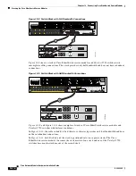
Figure 18-8 Switch Stack with Full Bandwidth Connections
Figure 18-9
shows a stack of Cisco EtherSwitch service modules and Catalyst 3750 switches with
incomplete cabling connections. This stack provides only half bandwidth and does not have redundant
connections.
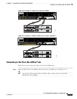
Figure 18-9 Switch Stack with Half Bandwidth Connections
Figure 18-10
and
Figure 18-11
show examples of stacks of Cisco EtherSwitch service modules and
Catalyst 3750 switches with failover conditions.
In
Figure 18-10
, the cable in link B is bad; therefore, this stack provides only half bandwidth and does
not have redundant connections.
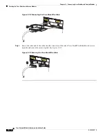
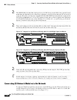
In
Figure 18-11
, link B is bad, and the stack is partitioned into two separate stacks. The Cisco
EtherSwitch service module 1 becomes the stack master of one stack and one of the Catalyst 3750
switches becomes the stack master of the second stack.
121915
A= ACT
FE 0/1
PVDM2 PVDM1 PVDM0
AIM1
AIM0
FE 0/0
S= SPEED
A= FDX
A= LINK
A
F
S
L
A
F
S
L
24x
SYST
MASTR
S
TAT
DUPLX
SPEED
ST
A
C
K
LINE PWR
MODE
EN
LASERPRODUKT DER KLASSE 1
1
PRODUCTO LASER CLASE 1
PRODUIT LASER DE CLASSE 1
CLASS 1 LASER PRODUCT
ARE ON THE FACEPLATE,
BE SECURED
ALL 6-32 THUMB SCREWS MUST
WHILE HULC STACK CABLES
GE 1
2x
2x
1x
4x
3x
6x
5x
8x
7x
11x
9x
12x
14x
13x
16x
15x
18x
17x
20x
19x
22x
21x
24x
23x
10x
A
C
B
NME-XD-
24ES-
1S-P
121918
A= ACT
FE 0/1
PVDM2 PVDM1 PVDM0
AIM1
AIM0
FE 0/0
S= SPEED
A= FDX
A= LINK
A
F
S
L
A
F
S
L
24x
SYST
MASTR
S
TAT
DUPLX
SPEED
ST
A
C
K
LINE PWR
MODE
EN
LASERPRODUKT DER KLASSE 1
1
PRODUCTO LASER CLASE 1
PRODUIT LASER DE CLASSE 1
CLASS 1 LASER PRODUCT
ARE ON THE FACEPLATE,
BE SECURED
ALL 6-32 THUMB SCREWS MUST
WHILE HULC STACK CABLES
GE 1
2x
2x
1x
4x
3x
6x
5x
8x
7x
11x
9x
12x
14x
13x
16x
15x
18x
17x
20x
19x
22x
21x
24x
23x
10x
A
B
STACK 2
STACK 2
NME-XD-
24ES-
1S-P

