28-6
Cisco Network Modules Hardware Installation Guide
OL-2485-20
Chapter 28 Connecting Cisco High-Density Extension Modules
Connecting Cisco High-Density Extension Modules to the Network
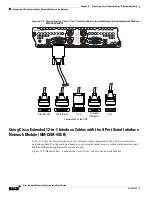
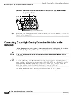
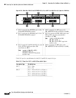
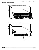
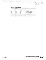
Figure 28-3 Label Locations for Expansion Modules on Cisco High-Density Expansion Modules
Step 7
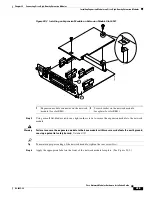
Install the network module into the router. (See the
“Installing Cisco Network Modules in Cisco Access
Routers” section on page 2-5
.)
Connecting Cisco High-Density Extension Modules to the
Network
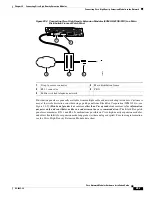
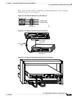
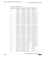
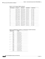
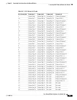
The Cisco high-density extension module is connected to a distribution frame or patch panel with an
RJ-21 cable. (See
Figure 28-4
.) RJ-21 cables are not provided with the network module.
Warning
Do not work on the system or connect or disconnect cables during periods of lightning activity.
Statement 1001
Caution
To comply with the Telcordia GR-1089 NEBS standard for electromagnetic compatibility and safety,
connect the 8-port analog voice/fax expansion module (EM-HDA-8FXS) and 4-port digital voice/fax
expansion module (EM-4BRI-NT/TE) only to intrabuilding or nonexposed wiring or cabling. The
intrabuilding cable must be shielded and the shield must be grounded at both ends.
For ordering information, see the
“Obtaining Technical Assistance” section on page xi
.
EVM-HD
EM0
1
26
EM1
8FXS/DID
None
None
EM
1
EM
0
103158
Apply label for EM1 here
Apply label for EM0 here

