7-4
Cisco Network Modules Hardware Installation Guide
OL-2485-20
Chapter 7 Connecting ISDN PRI Network Modules
Channelized T1/E1 PRI Network Modules with G.703
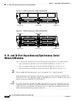
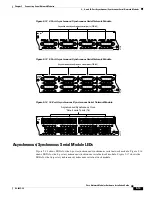
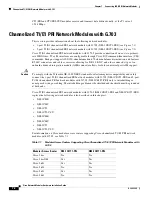
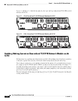
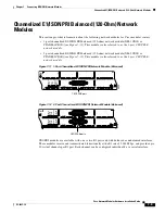
Figure 7-1
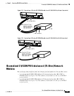
and
Figure 7-2
show the faceplates for the 1-port and 2-port channelized T1/E1 PRI network
modules with G.703.
Figure 7-1
1-Port Channelized T1/E1 PRI Network Module with G.703
Figure 7-2
2-Port Channelized T1/E1 PRI Network Module with G.703
Enabling Wetting Current on Channelized T1/E1 PRI Network Modules with
G.703
Wetting current is a small amount of electrical current (60 to 140 milliamps) sent from the central office
to the card to prevent the corrosion of electrical contacts in the module network connection.
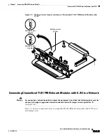
The wetting current feature can be enabled or disabled by the end user. It is controlled by the location
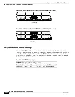
of a jumper on the J8 (CTLR 0) and J9 (CTLR 1) connectors on the network module. (See
Figure 7-3
.)
To enable the wetting current feature, connect pins 1 and 2 on the J8 and J9 connectors with the jumper.
To disable the wetting current feature, either remove the jumper completely, or use the jumper to connect
pins 2 and 3 on the J8 and J9 connectors.
The card is shipped with the jumper connecting pins 2 and 3 on the J8 and J9 connectors, disabling the
wetting current feature.
RX
MON
NM-1CE1T1-PRI
EN
AIM
TX
MON
CD
LP
RA
LA
C0
CTLR 0
T1
E1-BAL
E1-UNBAL
82886
RX
MON
NM-2CE1T1-PRI
CD
LP
RA
LA
T1
E1-BAL
E1-UNBAL
EN
AIM
TX
MON
CD
LP
RA
LA
C1
C0
CTLR 1
CTLR 0
T1
E1-BAL
E1-UNBAL
82887

