16-6
Cisco Network Modules Hardware Installation Guide
OL-2485-20
Chapter 16 Connecting High-Density Analog Telephony Network Modules
High-Density Analog Telephony Network Module LEDs
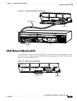
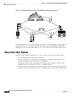
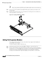
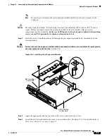
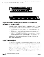
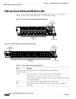
Figure 16-5 Label Locations for Expansion Ports
High-Density Analog Telephony Network Module LEDs
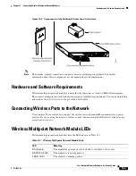
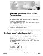
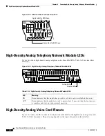
Figure 16-6
shows high-density analog telephony network module LEDs.
Table 16-3
describes their
meaning.
Figure 16-6 High-Density Analog Telephony Network Module LEDs
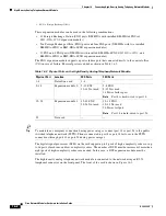
High-Density Analog Voice Card Pinouts
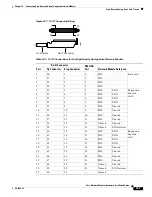
Figure 16-7
shows the RJ-21 connector wiring for the cable used for the high-density analog voice card;
Table 16-4
lists the pinouts. The port usage depends on the type of expansion cards installed.
NM-
HDA
1
26
Port
1-
4
5-
14
15-
24
# Type
4 FXS
62693
Apply label for EM1 here
Apply label for EM0 here
Table 16-3 High-Density Analog Telephony Network Module LEDs
LED
Meaning
EN
Green indicates that the module has passed its self-tests and is available to the router.
ACT
Green indicates that the module is ready to process data. It goes on when the boot process
is complete and stays on during normal operation.
NM-
HDA
1
25
ACT
26
50
EN
62296
Active LED
Enable LED
Port
1-
4
5-
14
15-
24
# Type
4 FXS

