5-14
Cisco Network Modules Hardware Installation Guide
OL-2485-20
Chapter 5 Connecting Serial Network Modules
4-, 8-, and 16-Port Asynchronous/Synchronous Serial Network Modules
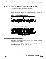
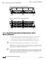
Figure 5-15 4-Port Asynchronous/Synchronous Serial Network Module LEDs
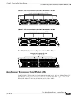
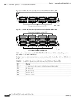
Figure 5-16 8-Port Asynchronous/Synchronous Serial Network Module LEDs
All network modules have an enable (EN) LED. This LED indicates that the module has passed its
self-tests and is available to the router.
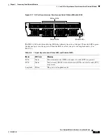
Each port on an asynchronous/synchronous serial network module also has the additional LEDs shown
in
Table 5-8
.
CN/LP
2
1
0
3
RXC
RXD
TXC
TXD
CN/LP RXC
RXD
TXC
TXD
CN/LP RXC
RXD
TXC
TXD
CN/LP RXC
RXD
TXC
TXD
EN
SERIAL
A/S
H7268
Asynchronous/synchronous serial port LEDs
Enable LED
CN/LP
2
1
0
3
RXC
RXD
TXC
TXD
CN/LP RXC
RXD
TXC
TXD
CN/LP RXC
RXD
TXC
TXD
CN/LP RXC
RXD
TXC
TXD
EN
SERIAL
A/S
H7269
CN/LP
6
5
4
7
RXC
RXD
TXC
TXD
CN/LP RXC
RXD
TXC
TXD
CN/LP RXC
RXD
TXC
TXD
CN/LP RXC
RXD
TXC
TXD
Asynchronous/synchronous serial port LEDs
Asynchronous/synchronous serial port LEDs
Enable LED
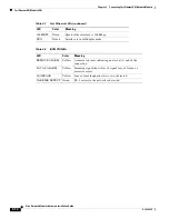
Table 5-8
4- and 8-Port Asynchronous/Synchronous Serial Network Module LEDs
LED
Meaning
CN/LP
In connect mode when green, in loopback mode when yellow
RXC
Receive clock
RXD
Receive activity
TXC
Transmit clock
TXD
Transmit activity

