10-5
Cisco Network Modules Hardware Installation Guide
OL-2485-20
Chapter 10 Connecting Analog Modem Network Modules
Connecting the Modules to the Telephone Network
Connecting the Modules to the Telephone Network
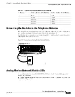
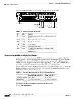
Each analog modem network module provides 8 or 16 RJ-11 jacks for standard modular cables. These
ports are color-coded pink. Cables are not provided with the network module.
To establish an analog connection, use a straight-through RJ-11 modular cable to connect the jack to a
wall telephone outlet. (See
Figure 10-5
.)
Figure 10-5 Connecting an Analog Modem Network Module
Analog Modem Network Module LEDs
All network modules have an enable (EN) LED. This LED indicates that the module has passed its
self-tests and is available.
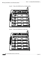
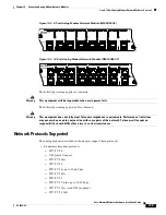
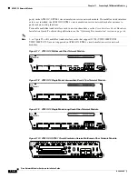
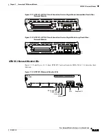
Each modem in the module has an in use (IN USE) LED that lights when the modem is off-hook. (See
Figure 10-6
and
Figure 10-7
.)
2
65–72
65–80
3
97–104
97–112
4
129–136
129–144
5
161–168
161–176
6
193–200
193–208
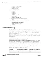
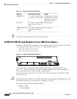
Table 10-1
16- and 32-Port Analog Module Interface Numbering
Slot Number
Interface Numbers (8-Port Module)
Interface Numbers (16-Port Module)
EN
7
6
5
4
3
2
1
0
15
14
13
12
11
10
9
8
IN USE
IN USE
95209
RJ-11 jack
Analog modem port (RJ-11)
Straight-through
RJ-11 cable
MODEMS
NM-16AM-V2

