C H A P T E R
17-1
Cisco Network Modules Hardware Installation Guide
OL-2485-20
17
Connecting
Ethernet Switch Network Modules
This chapter describes how to connect Ethernet switch network modules and contains the following
sections:
•
Ethernet Switch Network Modules, page 17-1
•
Requirements for Installing Two Ethernet Switch Network Modules in a Single Chassis, page 17-2
•
Power Considerations, page 17-2
•
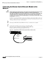
Connecting the Ethernet Switch Network Module to the Network, page 17-4
•
Adding an Optional Gigabit Ethernet Expansion Board, page 17-5
•
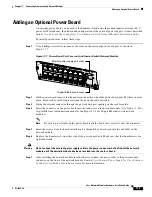
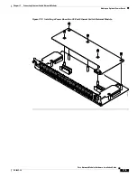
Adding an Optional Power Board, page 17-7
•
Ethernet Switch Network Module LEDs, page 17-10
Tip
To determine whether your router supports a specific network module, see
Table 1-6 on page 1-16
.
Ethernet Switch Network Modules
This chapter explains how to install the 16- and 36-port Ethernet switch network modules. The Ethernet
switch network module is a modular, high-density voice network module that provides Layer 2
switching across Ethernet ports. The 16-port Ethernet switch network module has 16 10/100BASE-TX
ports and an optional 10/100/1000BASE-T Gigabit Ethernet port. The 36-port Ethernet switch network
module has 36 10/100BASE-TX ports and 2 optional 10/100/1000BASE-T Gigabit Ethernet ports. The
36-port Ethernet switch network module requires a double-wide slot. An optional power module can also
be added to provide inline power for IP telephones.
The10/100BASE-TX ports and Gigabit Ethernet ports on the Ethernet switch network module are
connected to the network using RJ-45 connectors on the front panel. The power module is connected to
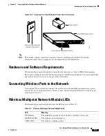
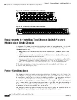
an external power supply using a power connection cable. The front of the 16-port card is shown in
Figure 17-1
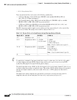
. The front panel of the 36-port card is shown in
Figure 17-2
.

