4-7
Cisco Network Modules Hardware Installation Guide
OL-2485-20
Chapter 4 Connecting Fast Ethernet-PRI Network Modules
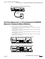
1-Port Fast Ethernet and 1- or 2-Port Channelized E1/ISDN PRI Balanced or Unbalanced Network Modules
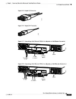
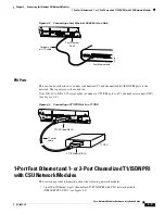
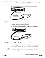
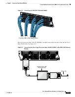
Figure 4-12 Connecting a CE1/PRI-B Port to an E1 CSU (DB-15-to-RJ-45 Connectors)
CE1/PRI-U Port
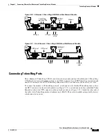
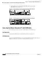
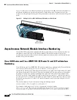
Use the appropriate cable to connect a CE1/PRI-U (75-ohm) port to an E1 CSU.
Figure 4-13
shows a
CSU with BNC connectors. These ports are color-coded tan.
Figure 4-13 Connecting a CE1/PRI-U Module to an E1 CSU (DB-15-to-BNC Connectors)
Setting Interfaces to Balanced or Unbalanced Termination
This section describes how to configure an E1 network module for balanced or unbalanced termination.
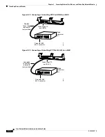
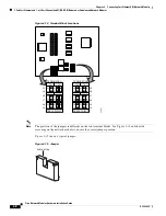
The module consists of two circuit boards, or cards. A terminal block and a set of five jumpers are
provided on each card to configure termination.
Figure 4-14
shows these terminal blocks.
Caution
To avoid damaging electrostatic discharge (ESD)-sensitive components, observe all ESD
precautions when handling the circuit boards.
LOOP
BACK
EN
FE-PRI
1FE-1CE1-B/U
LOCAL
ALARM
REMOTE
ALARM
CARRIER
DETECT
10/100BaseT
COLL
LINK
100Mbps
FDX
H7472
CE1/PRI port (DB-15)
RJ-45 jack
E1 cable for 120-ohm
balanced connections
with an RJ-45 connector
at the network end
CTRLR 0
LOOP
BACK
EN
FE-PRI
1FE-1CE1-B/U
LOCAL
ALARM
REMOTE
ALARM
CARRIER
DETECT
10/100BaseT
COLL
LINK
100Mbps
FDX
H7471
CE1/PRI-U
BNC connectors
E1 CSU
E1 cable for 75-ohm
unbalanced connections
with BNC connectors
at the network end
CTRLR 0


