39-6
Cisco Network Modules Hardware Installation Guide
OL-2485-20
Chapter 39 Connecting Cisco Analog Video Gateway Network Modules
How to Install, Connect, or Replace the EVM-IPVS-16A Network Module
•
Performing Online Insertion and Removal of the EVM-IPVS-16A Network Module, page 39-9
Installing the EVM-IPVS-16A Network Module in the Router Chassis
To install the EVM-IPVS-16A network module in the router chassis, see the “
Installing Cisco Network
Modules in Cisco Access Routers
” chapter of the
Cisco Network Modules Hardware Installation Guide
.
Note
The EVM-IPVS-16A network module can only be installed in slots that support extension modules. For
information about which slots support extension modules, see
Table 1-1 on page 1-5
Wiring the Terminal Block Connectors
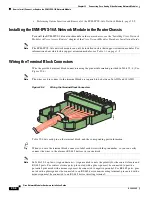
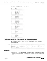
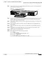
Wire the provided terminal block connectors using the pinout information provided in
Table 39-4
. (See
Figure 39-4
.)
Note
The wires used to connect to the terminal block are required to be between 26 AWG and 18 AWG.
Figure 39-4
Wiring the Terminal Block Connectors
Table 39-4
lists each pin on the terminal block, and the corresponding port information.
Tip
When you wire the terminal block connector, label each wire with the pin number, so you can easily
connect the wires to the alarm or RS-485 devices in your network.
Note
In
Table 39-4
a plus (+) sign and minus (–) sign are used to note the polarity for the contact closure and
RS-485 ports. For contact closure ports, pins noted with a plus sign must be connected to positive
potential; pins noted with a minus sign must be connected to negative potential. For RS-485 ports, pins
noted with a plus sign must be connected to an RS-485 device non-inverting terminal; pins noted with a
minus sign must be connected to an RS-485 device inverting terminal.
230462


