


34-23
Cisco Network Modules Hardware Installation Guide
OL-2485-20
Chapter 34 Connecting Cisco Network Admission Control Network Modules
Connecting NAC Network Modules
Shutting Down the NAC Network Module
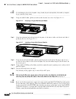
Press the shutdown button on the network module faceplate for less than 2 seconds to perform a graceful
shutdown of the hard disk before removing power from the router or before starting an online insertion
and removal (OIR) sequence on the router. The application may take up to 2 minutes to fully shut down.
Note
See the
Getting Started with NAC Network Modules in Cisco Access Routers
document on Cisco.com for
instructions that describe how to shut down the network module from the command line interface on the
router,
http://www.cisco.com/en/US/products/ps6128/prod_installation_guides_list.html
Caution
If you press the shutdown button for
more than 4 seconds
, a non-graceful shutdown of the hard disk will
occur and may cause file corruption on the network module’s hard disk. After a non-graceful shutdown,
the DISK and SYS LEDs remain lighted. Press the shutdown button for
less than 1 second
to gracefully
reboot the network module.
Connecting NAC Network Modules
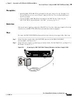
To connect Cisco NAC network modules to an external device use a straight-through two-pair
Category 5 unshielded twisted-pair (UTP) cable and connect the RJ-45 Gigabit Ethernet port on the
network module to a switch, hub, repeater, or other Gigabit Ethernet network device.
Warning
To comply with the Telcordia GR-1089 NEBS standard for electromagnetic compatibility and safety,
connect the Network Admission Control Network Modules (NME-NAC-K9) only to intra-building or
unexposed wiring or cable. The intrabuilding cable must be shielded and the shield must be grounded
at both ends. The intra-building port(s) of the equipment or subassembly must not be metallically
connected to interfaces that connect to the OSP or its wiring. These interfaces are designed for use
as intra-building interfaces only (Type 2 or Type 4 ports as described in GR-1089-CORE, Issue 4) and
require isolation from the exposed OSP cabling. The addition of Primary Protectors is not sufficient
protection in order to connect these interfaces metallically to OSP wiring.
Note
RJ-45 cables are not available from Cisco Systems. These cables are widely available and must be
Category 5 cables.