16-3
Cisco Network Modules Hardware Installation Guide
OL-2485-20
Chapter 16 Connecting High-Density Analog Telephony Network Modules
Connecting the High-Density Analog Telephony Network Module to the Network
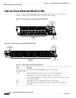
Figure 16-1 High-Density Analog Telephony Network Module
Connecting the High-Density Analog Telephony Network
Module to the Network
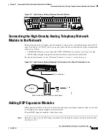
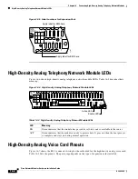
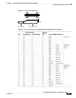
The high-density analog telephony network module is connected to a distribution frame with an RJ-21
cable. (See
Figure 16-2
.) RJ-21 cables are not provided with the network module. Some recommended
cables are as follows:
•
253PP10GYADI male-to-male cable and 253PC10GYADI male-to-female cable from Gray Bar
•
AT125-SM patch panel (supports both male and female connection) from Gray Bar
For ordering information, see the
“Obtaining Technical Assistance” section on page xi
.
Figure 16-2 High-Density Analog Telephony Card Connected to a Main Distribution Frame
Adding DSP Expansion Modules
DSP expansion modules can be used if more than eight ports using high-complexity codecs are needed
on the high-density analog telephony network module.
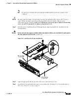
To install DSP expansion modules, follow these steps:
Step 1
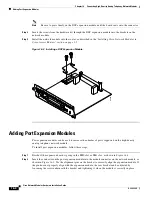
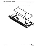
Insert the connector on the DSP expansion module into the module connector on the network module.
(See
Figure 16-3
.)
NM-
HDA
1
25
ACT
26
50
EN
62292
Port
1-
4
5-
14
15-
24
# Type
4 FXS
NM-
HDA
1
25
ACT
26
50
EN
Port
1-
4
5-
14
15-
24
# Type
4 FXS
62293
Main distribution frame (MDF) or patch panel
PBX
RJ-21 connector
PSTN


