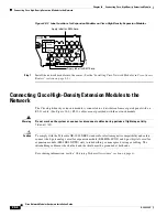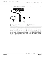
29-8
Cisco Network Modules Hardware Installation Guide
OL-2485-20
Chapter 29 Connecting Alarm Interface Controller Network Modules
AIC Network Module LEDs
AIC Network Module LEDs
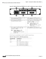
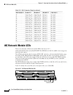
This section describes AIC network module LEDs. (See
Figure 29-7
.)
All network modules have an enable (EN) LED. This LED indicates that the module is receiving power
from the router chassis.
The AIC network module also has a status (STAT) LED, which is a software-controlled bicolor (green
and orange) LED. Both the EN and STAT LEDs turn on when the router is powered up, recycled, or
power-cycled, or the AIC is hot-swapped. When the AIC starts to boot up, the STAT LED is initially
turned off. It turns green when the software has initialized, has passed POST, and has established
communication with IOS.
The STAT LED turns from green to orange when POST has failed or when the software encounters any
other fatal fault in its firmware during normal operation.
Table 29-4
defines the state of the card with respect to the states of the LEDs.
Figure 29-7 AIC Network Module LEDs
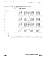
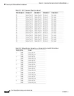
19
Alarm Neg 19
Alarm Neg 44
Not used
Not used
44
Alarm Pos 19
Alarm Pos 44
Not used
Not used
20
Alarm Neg 20
Alarm Neg 45
Not used
Not used
45
Alarm Pos 20
Alarm Pos 45
Not used
Not used
21
Alarm Neg 21
Alarm Neg 46
Not used
Not used
46
Alarm Pos 21
Alarm Pos 46
Not used
Not used
22
Alarm Neg 22
Alarm Neg 47
Not used
Not used
47
Alarm Pos 22
Alarm Pos 47
Not used
Not used
23
Alarm Neg 23
Alarm Neg 48
Not used
Not used
48
Alarm Pos 23
Alarm Pos 48
Not used
Not used
24
Alarm Neg 24
Alarm Neg 49
Not used
Not used
49
Alarm Pos 24
Alarm Pos 49
Not used
Not used
25
Alarm Neg 25
Alarm Neg 50
Not used
Not used
50
Alarm Pos 25
Alarm Pos 50
Not used
Not used
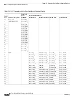
Table 29-3 AIC-2 Connector Pinouts (continued)
Telco Connector
Connector 1
Connector 2
Connector 3
Connector 4
EN
AIC-64
CONN 2
STAT
37422
CONN 4
CONN 1
CONN 3
Status LED
Enable LED

