6-5
Cisco Network Modules Hardware Installation Guide
OL-2485-20
Chapter 6 Connecting ISDN BRI Network Modules
4- and 8-Port ISDN BRI U Network Modules
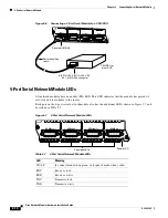
BRI U Module LEDs
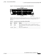
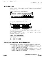
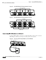
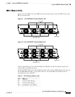
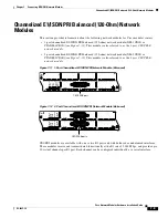
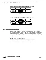
Figure 6-9
shows LEDs for the 4-port BRI U network module.
Figure 6-10
shows LEDs for the 8-port
BRI U network module.
Figure 6-9
4-Port ISDN BRI U Network Module LEDs
Figure 6-10 8-Port ISDN BRI U Network Module LEDs
All network modules have an enable (EN) LED. This LED indicates that the module has passed its
self-tests and is available to the router.
In addition, BRI U modules have three LEDs for each port. Two of these LEDs indicate call activity on
the two ISDN BRI B channels, as described in
Table 6-2
. The third LED, labeled NT1, indicates
synchronization status of the NT1.
BRI 3
EN
BRI
U
H7265
B1
B2
BRI 2
B1
B2
BRI 1
B1
B2
BRI 0
B1
B2
NT1
NT1
NT1
NT1
NT1 LEDs
ISDN BRI LEDs
Enable LED
BRI 3
EN
BRI
U
H7264
B1
B2
BRI 2
B1
B2
BRI 1
B1
B2
BRI 0
B1
B2
NT1
NT1
NT1
NT1
BRI 7
B1
B2
BRI 6
B1
B2
BRI 5
B1
B2
BRI 4
B1
B2
NT1
NT1
NT1
NT1
NT1 LEDs
ISDN BRI LEDs
Enable LED
Table 6-2
BRI U Network Modules LEDs
LED
Meaning
B1
Activity on B1 channel
B2
Activity on B2 channel
NT1
Synchronous status of NT1

