25-2
Cisco Network Modules Hardware Installation Guide
OL-2485-20
Chapter 25 Connecting Cisco Network Analysis Modules
Network Analysis Module Overview
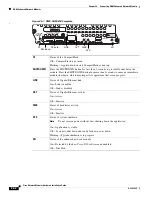
Figure 25-1 Cisco Network Analysis Module (NM-NAM) Faceplate and LEDs
Connecting Cisco Network Analysis Modules to the Network
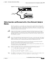
To connect a network analysis module to the network, use a straight-through 2-pair Category 5
unshielded twisted-pair (UTP) cable to connect the RJ-45 port on the network analysis module to a
switch, hub, repeater, server, or other network device. (See
Figure 25-2
.)
Caution
To comply with the Telcordia GR-1089 NEBS standard for electromagnetic compatibility and safety,
connect the network analysis module (NM-NAM) only to intrabuilding or nonexposed wiring or cabling.
The intrabuilding cable must be shielded and the shield must be grounded at both ends.
Note
RJ-45 cables are not available from Cisco Systems. These cables are widely available and must be
Category 5 cables.
Table 25-1 Cisco Network Analysis Module (NM-NAM) LEDs
Callout
LED
Meaning
1
DISK
There is activity on the hard drive.
2
LINK
The Fast Ethernet connection is available to the network module.
3
ACT
There is activity on the Fast Ethernet connection.
4
PWR
Power is available to the network module.
5
EN
The module has passed self-test and is available to the router.
NM-NAM
EN
PWR
FastEthernet 0
DISK
LINK
ACT
WARNING!!
Shut down NM-NAM application
before removing or power cycling.
CF
95749
2
3
4
5
1


