


REAR AXLE DIFFERENTIAL
4B-5
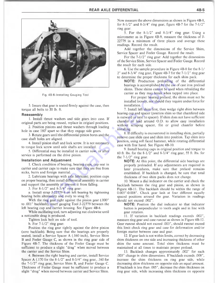
Fig. 4 B -6 —In s ta llin g G a u g in g T o o l
5.
Insure that gear is seated firmly against the case, then
torque all bolts to 50 lb. ft.
Reassembly
1. Install thrust washers and side gears into case. If
original parts are being reused, replace in origianl positions.
2. Position pinions and thrust washers through loading
hole in case 180° apart so that they engage side gears.
3. R otate gears until the differential pinion bores and the
case shaft holes are aligned.
4. Install pinion shaft and lock screw. It is not necessary
to torque lock screw until axle shafts are installed.
5. Differential may be installed in carrier now, or after
service is perform ed on the drive pinion.
Installation and Adjustm ent
1. Check condition of bearing, bearing cups, cup seat in
carrier and carrier caps to make sure that they are free from
nicks, burrs and foreign material.
2. Lubricate bearings with axle lubricant; position cups
on proper bearing, then install differential assembly in carrier
and support the assembly to prevent it from falling.
3. For 8-1/2" and 8-3/4" ring gear:
a. Install strap J-22779-6 on left bearing by tightening
bearing bolts alternately and evely to snug fit.
W ith the ring gear tight against the pinion gear (.000"
to .001" backlash), insert gauging Tool J-22779 between the
left bearing cup and carrier housing. See Figure 4B-6.
While oscillating tool, turn adjusting nut clockwise until
a noticeable drag is produced.
Tighten lock bolt on side of tool.
b. For 7-1/2" ring gear:
Position the ring gear tightly against the drive pinion
(zero backlash). Being sure that the bearings are properly
seated, install a Service Spacer A (.160 inch), Service Shim
B and Feeler G auge C, as shown in the ring gear side of
Figure 4B-7. The thickness of the Feeler Gauge m ust be
sufficient to produce a slight "drag" when moved between
the carrier and the Service Shim.
4. Between the right bearing and carrier, install Service
Spacer A (.170 for the 8-1/2" and 8-3/4" ring gear, .160 for
the 7-1/2" ring gear, Service Shim B, and Feeler Gauge C.
Thickness of Feeler Gauge m ust be sufficient to produce a
slight "drag" when moved between carrier and Service Shim.
Now measure the above dimensions as shown in Figure 4B-8,
for 8-1/2" and 8-3/4" ring gear, figure 4B-7 for the 7-1/2"
ring gear.
5. F or the 8-1/2" and 8-3/4" ring gear: Using a
m icrom eter as in Figure 4B-9, measure the thickness of J-
22779 in a m inim um of three places and average these
readings. Record the result.
Add together the dimensions of the Service Shim,
Service Spacer and Feeler Gauge. Record the result.
F or the 7-1/2" ring gear: A dd together the dimesnions
of the Service Shim, Service Spacer and Feeler Gauge. Record
the result for each side.
6. Use the sample procedure in Figure 4B-8 for the 8-1/
2" and 8-3/4" ring gear, Figure 4B-7 for the 7-1/2" ring gear
to determine the proper thickness for each shim pack.
NOTE:
Production preloading of the differential
bearings is accomplished by the use of cast iron preload
shims. These shims cannot be used when rebuilding the
carrier as they may break when tapped into place.
F or proper bearing prelaod, the shims must not be
installed loosely, nor should they require undue force for
installation.
7. Install left shim first, then wedge right shim between
bearing cup and spacer (position shim so that chamfered side
is outw ard or next to spacer). If shim does not have sufficient
chamfer or lead around O.D. to allow easy installation
without scraping spacer, file or grind cham fer before
installing.
8. If difficulty is encountered in installing shim, partially
remove case slide case and shim into position. Tap shim into
position, using soft faced hammer, while rotating differential
case with free hand. See Figure 4B-10.
9. Install bearing caps in original position and torque to
60 ft. lbs. for the 8-1/2" and 8-3/4" ring gear, 55 ft. lbs. for
the 7-1/2" ring gear.
NOTE:
A t this point, the differential side bearings are
properly preloaded. If any adjustm ents are required in
later procedures, m ake sure that prelaod remains
established. If backlash is changed, be sure that total
thickness of two shim packs does not change.
10. M ount a dial indicator on the carrier and check the
backlash between the ring gear and pinion, as shown in
Figure 4B-11. The backlash should be within the range of
0.005"-0.008". Check gear lash at four different equally
spaced positions around the gear. Variation in readings
should not exceed .002".
NOTE:
Position the dial indicator so that indicator
button is perpendicular to tooth angle and in line with
gear rotation.
11. If variation in backlash readings exceeds .002",
measure ring gear and case runout as shown in Figure 4B-12.
G ear runout should not exceed .003", should runout exceed
this limit check ring gear and case for deformation a n d /o r
foreign m atter between case and gear.
12. If gear lash is not within limits, correct by decreasing
shim thickness on one side and increasing thickness of other
shim the same am ount. Total shim thickness m ust be
m aintained at all times to m aintain proper preload.
13. Backlash changes approxim ately .002" for each
.003" change in shim dimensions. If backlash exceeds .008",
increase the shim thickness on ring gear side, while
decreasing shim thickness on opposite side an equal am ount.
If backlash is less than .005", decrease the shim thickness on
ring gear side, while increasing shim thickness on opposite
Summary of Contents for 1977 10 Series
Page 1: ......
Page 2: ......
Page 4: ......
Page 6: ......
Page 42: ......
Page 65: ...STEERING 3B 23 Fig 3B 65 M easure Back and Remark Housing Fig 3B 67 Tighten Lock Nut...
Page 86: ...4B 14 OVERHAUL MANUAL Fig 4B 28 Gear Teeth C ontact Pattern Check...
Page 125: ...REAR AXLE DIFFERENTIAL 4B 53 Fig 18E Gear Teeth Contact Pattern Check...
Page 156: ......
Page 164: ...4C 8 OVERHAUL MANUAL Fig 4C 12 Gear Tooth Pattern Contact Pattern...
Page 166: ......
Page 194: ......
Page 284: ......
Page 320: ......
Page 322: ...400 7A 2 OVERHAUL MANUAL Fig 7A 1C Side Cross Section Typical...
Page 444: ...7B 64 OVERHAUL MANUAL Fig 7B 11S M od el 2 03 Transfer Case Exploded V iew...
Page 458: ......
Page 466: ......
Page 467: ......
Page 468: ......