


REAR AXLE DIFFERENTIAL
4B-77
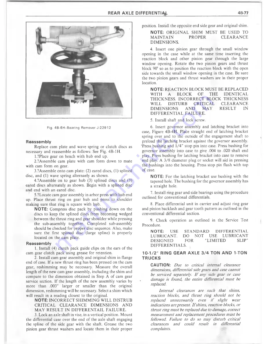
Fig. 4 B -6 H ~ B e a rin g R em over J -2 2 9 1 2
Reassembly
Replace cam plate and wave spring or clutch discs as
necessary and reassemble as follows: See Fig. 4B-1H.
1.?Place gear on bench with hub end up.
2.?Assemble cam plate with cam form down to mate
with cam form on gear.
3.?Assemble onto cam plate: (2) eared discs, (1) splined
disc, and (1) wave spring alternaely as shown.
4.?Assemble on to gear hub (3) splined discs and (3)
eared discs alternately as shown. Begin with a splined disc
and end with an eared disc.
5.?Locate cam gear assembly in arbor press with hub end
up. Place thrust ring on gear hub and press to shoulder
making sure that ring is square with hub.
NOTE:
Compress disc pack by pushing down on the
discs to keep the splined discs from becoming wedged
between the thrust ring and gear shoulder while pressing
the sub-assembly together. Completed sub-assembly
should be checked for proper disc sequence. Also, make
sure the first splined disc (large spline) is properly
located on the cam plate.
Reassembly
1. Install (4) clutch pack guide clips on the ears of the
cam gear clutch pack using grease for retention.
2. Install cam gear assembly and original shim in flange
end of case. If a new thrust ring has been pressed on the cam
gear, reshimming may be necessary. M easure the overall
length of the new cam gear assembly, including the shim and
com pare to the dimension obtained in Step A of cam gear
service section. If the length of the new assembly varies by
m ore than .003" larger or smaller than the original
dimension, reshimming will be necessary. Select a shim which
will result in a reading closest to the original.
NOTE:
IN C O R R E C T SH IM M IN G W ILL D ISTRU B
C R IT IC A L C L E A R A N C E D IM EN SIO N S A N D
M AY R ESU LT IN D IF F E R E N T A IL FA IL U R E .
3. Lock an axle shaft in vise, in a vertical position. M ount
the differential case over the end of the axle shaft engaging
the spline of the side gear with the shaft. Grease the two
pinion gear thrust washers and locate them in their proper
position. Install the opposite end side gear and original shim.
NOTE:
O R IG IN A L SHIM M UST BE USED TO
M A IN T A IN
P R O P E R
C L E A R A N C E
D IM EN SIO N S.
4. Insert one pinion gear through the small window
opening in the case while at the same time inserting the
reaction block and other pinion gear through the large
window opening. R otate the two pinion gears and thrust
block 90° so as to position the reaction block with the open
side towards the small window opening in the case. Be sure
the two pinion gears and thrust washers are in their proper
location.
NOTE:
R E A C T IO N BLO CK M UST BE R E PL A C E D
W ITH
A
B LO C K
O F
T H E
ID E N T IC A L
T H IC K N ESS. IN C O R R E C T BLOCK T H IC K N ESS
W ILL
D ISTU R B
C R IT IC A L
C L E A R A N C E
D IM E N SIO N S
A N D
MAY
RESU LT
IN
D IF F E R E N T IA L FA IL U R E .
5. Install shaft and lock screw.
6. Insert governor assembly and latching bracket into
case, Figure 4B-4H. Place straight end of latching bracket
spring over and to the outside of the engagement shaft to
preload the latching bracket against the governor assembly.
T ress bushing and 1/4" stop pin into case. Press bushing for
governor assembly into case to give .004 to .020 shaft end
play. Press bushing for latching bracket into case to remove
end play. A 3 /8 diam eter plug or socket will aid in pressing
the bushings into the housing. Press stop pin flush with top
of case.
NOTE:
F or the latching bracket use bushing with the
tapered hole. The bushing for the governor assembly has
a straight hole.
7. Install ring gear and side bearings using the procedure
outlined, for conventional differentials.
8. Place differential unit in carrier and adjust ring gear
and pinion backlash and gear tooth pattern as outlined in the
conventional differential section.
9. Check operation as outlined in the Service Test
Procedure.
NOTE:
USE
ST A N D A R D
D IF F E R E N T IA L
L U B R IC A N T.
DO
N O T
USE
L U B R IC A N T
D E S IG N E D
FO R
"L IM IT E D
SLIP"
D IF F E R E N T IA L S .
10-1/2" RING GEAR AXLE 3 /4 TON AND 1-TON
TRUCKS
CAUTION:
Due to critical internal clearance
dimensions, differential side gears and case cannot
be serviced separately. I f any side gear or case
damage is found, the entire differential m ust be
replaced.
Internal clearances are such that shims,
reaction blocks, and thrust ring should not be
replaced unnecessarily even i f slight wear
indications are present. I f shims, reaction blocks, or
thrust ring m ust be replaced due to damage, correct
measurement and replacement procedures m ust be
followed. Failure to do so may disturb critical
clearances and could result in differential
complaints.
Summary of Contents for 1977 10 Series
Page 1: ......
Page 2: ......
Page 4: ......
Page 6: ......
Page 42: ......
Page 65: ...STEERING 3B 23 Fig 3B 65 M easure Back and Remark Housing Fig 3B 67 Tighten Lock Nut...
Page 86: ...4B 14 OVERHAUL MANUAL Fig 4B 28 Gear Teeth C ontact Pattern Check...
Page 125: ...REAR AXLE DIFFERENTIAL 4B 53 Fig 18E Gear Teeth Contact Pattern Check...
Page 156: ......
Page 164: ...4C 8 OVERHAUL MANUAL Fig 4C 12 Gear Tooth Pattern Contact Pattern...
Page 166: ......
Page 194: ......
Page 284: ......
Page 320: ......
Page 322: ...400 7A 2 OVERHAUL MANUAL Fig 7A 1C Side Cross Section Typical...
Page 444: ...7B 64 OVERHAUL MANUAL Fig 7B 11S M od el 2 03 Transfer Case Exploded V iew...
Page 458: ......
Page 466: ......
Page 467: ......
Page 468: ......