


IB-14
OVERHAUL MANUAL
Fig. 3 9 - A s s e m b l i n g C y lin d e r Halves
Dial Indicator Set J-8001-3 may be used to determ ine proper
thrust race size.
P R O P E R SELE C T IO N O F T H R U ST RACES A N D
BALL SEATS IS O F E X T R E M E IM PO R T A N C E .
15.
M easure clearance between rear ball of No. 1 Piston
and axial plate, in following manner:
a. Select a suitable com bination of well-oiled Feeler
Gage leaves to fit snugly between ball and axial plate.
b. A ttach a spring scale, reading in 1-ounce increments,
to the feeler gage. A distributor point checking scale or
Spring Scale J-544 may be used.
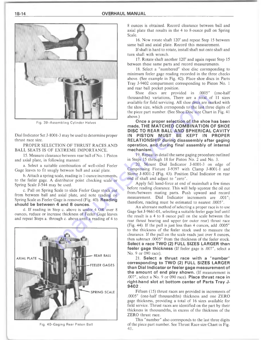
c. Pull on Spring Scale to slide Feeler Gage stock out
from between ball and axial plate, and note reading on
Spring Scale as Feeler Gage is removed (Fig. 40).
Reading
should be between 4 and 8 ounces.
d. If reading in Step c. above is under 4 OR over 8
ounces, reduce or increase thickness of Feeler Gage leaves
and repeat Steps a. through c. above until a reading of 4 to
8 ounces is obtained. Record clearance between ball and
axial plate that results in the 4 to 8-ounce pull on Spring
Scale.
16. Now rotate shaft 120° and repeat Step 15 between
same ball and axial plate. Record this measurement.
If shaft is hard to rotate, install shaft nut onto shaft and
turn shaft with wrench.
17. R otate shaft another 120° and again repeat Step 15
between these same parts and record measurements.
18. Select a "num bered" shoe disc corresponding to
minimum feeler gage reading recorded in the three checks
above. (See example in Fig. 42). Place shoe discs in Parts
Tray J-9402 com partm ent corresponding to Piston No. 1
and rear ball pocket position.
Shoe
discs
are
provided
in
.0005"
(one-half
thousandths) variations, There are a total of 11 sizes
available for field servicing. All shoe discs are m arked with
the shoe size, which corresponds to the last three digits of
the piece part number. (See Shoe Disc size Chart in Fig. 41
above.)
Once a proper selection of the shoe has been
made, THE M ATCHED C O M B IN A TIO N OF SHOE
DISC TO REAR BALL AND SPHERICAL CAVITY
IN
PISTON
M U ST
BE
KEPT
IN
PROPER
RELATIONSHIP during disassembly after gaging
operation, and during final assembly of internal
mechanism.
19. Repeat in detail the same gaging procedure outlined
in Steps 15 through 18 for Piston No. 2 and No. 3.
20. M ount Dial Indicator J-8001-3 on edge of
Compressing Fixture J-9397 with Clamp J-8001-1 and
Sleeve J-8001-2 (Fig. 43). Position Dial Indicator on rear
end of shaft and adjust to "zero".
Apply full hand-force at end of m ainshaft a few times
before reading clearance. This will help squeeze the oil out
from /betw een m ating parts. Push upward and record
measurement.
Dial Indicator increments are .001";
therefore, reading must be estim ated to nearest .0005".
An alternate m ethod of selecting a proper race is to use
Gage Set J-9661-01, selecting a suitable feeler gage leaf until
the result is a 4 to 8 ounce pull on the scale between the
rear thrust bearing and upper (or outer rear) thrust race
(Fig. 44). If the pull is just less than 4 ounces, add .0005"
to the thickness of the feeler stock used to measure the
clearance. If the pull on the scale reads just over 8 ounces,
then subtract .0005" from the thickness of the feeler stock.
Select a race TW O (2) FULL SIZES LARGER than
feeler gage thickness
(If feeler gage is .007", select a
No. 9 or 090 race).
2 1
.
Select a thrust race w ith a "number"
corresponding to TW O (2) FULL SIZES LARGER
than Dial Indicator or feeler gage measurement of
the amount of end play shown.
(If measurement is
.007", select a No. 9 or 090 race).
Place thrust race in
right-hand slot at bottom center of Parts Tray J-
9 4 0 2 .
Fifteen (15) thrust races are provided in increm ents of
.0005" (one-half thousandths) thickness and one Z E R O
gage thickness, providing a total of 16 sizes available for
field service. T hrust races are identified on the part by their
thickness in thousandths, in excess of the thickness of the
ZERO thrust race.
This "num ber" also corresponds to the last three digits
of the piece part number. See T hrust Race size C hart in Fig.
41.
A X IA L PLATE
REAR BALL
FEELER G A G E S
Fig. 40--G a g in g Rear Piston Ball
Summary of Contents for 1977 10 Series
Page 1: ......
Page 2: ......
Page 4: ......
Page 6: ......
Page 42: ......
Page 65: ...STEERING 3B 23 Fig 3B 65 M easure Back and Remark Housing Fig 3B 67 Tighten Lock Nut...
Page 86: ...4B 14 OVERHAUL MANUAL Fig 4B 28 Gear Teeth C ontact Pattern Check...
Page 125: ...REAR AXLE DIFFERENTIAL 4B 53 Fig 18E Gear Teeth Contact Pattern Check...
Page 156: ......
Page 164: ...4C 8 OVERHAUL MANUAL Fig 4C 12 Gear Tooth Pattern Contact Pattern...
Page 166: ......
Page 194: ......
Page 284: ......
Page 320: ......
Page 322: ...400 7A 2 OVERHAUL MANUAL Fig 7A 1C Side Cross Section Typical...
Page 444: ...7B 64 OVERHAUL MANUAL Fig 7B 11S M od el 2 03 Transfer Case Exploded V iew...
Page 458: ......
Page 466: ......
Page 467: ......
Page 468: ......