


CARBURETOR
6C-19
Fig. 6 C -5 4 --ln s ta llin g C h o ke Rod Lever
therm ostatic coil lever onto flats on interm ediate choke shaft.
Inside therm ostatic choke coil lever is properly aligned when
both inside and outside levers face tow ards fuel inlet. Install
inside lever retaining screw into end of interm ediate choke
shaft. Tighten securely.
6.
Using Tool J-23417, install lower choke rod lever into
cavity in float bowl. Install plastic tube seal into cavity on
choke housing before assembling choke housing to bowl.
Install choke housing to bowl sliding interm ediate choke
shaft into lower choke lever (Fig. 6C-54).
NOTE:
The interm ediate choke shaft lever and fast idle
cam are in correct relation when the tang on lever is
beneath the fast idle cam. D o not install choke cover and
coil assembly until inside coil lever is adjusted. Refer to
Service Section for adjustm ent procedures.
Float Bowl
M 4 M E M odel W ith Rear Vacuum Break
1. Holding down on fast idle cam (hot idle position),
install end of vacuum break rod in hole in interm ediate choke
lever.
2. Install end of vacuum break rod in slot in rear vacuum
break plunger head. Then- install rear vacuum break control
and bracket assembly to float bowl using two attaching
screws (Fig. 6C-48). Tighten securely.
NOTE:
D o not attach vacuum break hose until after the
vacuum break adjustm ent is complete. Refer to Service
Section for adjustm ent procedure.
A ll Models
3. If removed, install air baffle in secondary side of float
bowl with notches toward the top. Top edge of baffle must
be flush with bowl casting.
4. If removed, install baffle in pum p well fill slot.
5. Install pum p discharge check ball and retainer in
passage next to pum p well. Tighten retainer securely.
6. Install prim ary main metering jets (if removed) (Fig.
6C-47).
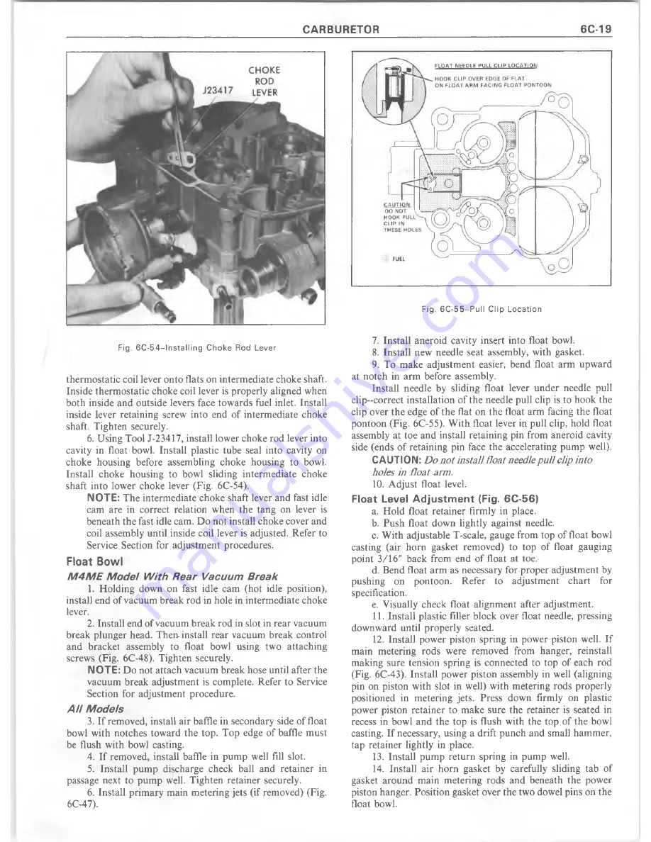
Fig. 6 C -5 5 --P u ll C lip L o ca tio n
7. Install aneroid cavity insert into float bowl.
8. Install new needle seat assembly, with gasket.
9. To make adjustm ent easier, bend float arm upw ard
at notch in arm before assembly.
Install needle by sliding float lever under needle pull
clip -co rrect installation of the needle pull clip is to hook the
clip over the edge of the flat on the float arm facing the float
pontoon (Fig. 6C-55). W ith float lever in pull clip, hold float
assembly at toe and install retaining pin from aneroid cavity
side (ends of retaining pin face the accelerating pum p well).
CAUTION:
Do not install float needle pull clip into
holes in float arm.
10. A djust float level.
Float Level Adjustm ent (Fig. 6C-56)
a. Hold float retainer firmly in place.
b. Push float down lightly against needle.
c. W ith adjustable T-scale, gauge from top of float bowl
casting (air horn gasket removed) to top of float gauging
point 3/16" back from end of float at toe.
d. Bend float arm as necessary for proper adjustm ent by
pushing on pontoon. Refer to adjustm ent chart for
specification.
e. Visually check float alignm ent after adjustment.
11. Install plastic filler block over float needle, pressing
downward until properly seated.
12. Install power piston spring in power piston well. If
main metering rods were removed from hanger, reinstall
making sure tension spring is connected to top of each rod
(Fig. 6C-43). Install power piston assembly in well (aligning
pin on piston with slot in well) with metering rods properly
positioned in metering jets. Press down firmly on plastic
power piston retainer to m ake sure the retainer is seated in
recess in bowl and the top is flush with the top of the bowl
casting. If necessary, using a drift punch and small hammer,
tap retainer lightly in place.
13. Install pum p return spring in pump well.
14. Install air horn gasket by carefully sliding tab of
gasket around m ain metering rods and beneath the power
piston hanger. Position gasket over the two dowel pins on the
float bowl.
Summary of Contents for 1977 10 Series
Page 1: ......
Page 2: ......
Page 4: ......
Page 6: ......
Page 42: ......
Page 65: ...STEERING 3B 23 Fig 3B 65 M easure Back and Remark Housing Fig 3B 67 Tighten Lock Nut...
Page 86: ...4B 14 OVERHAUL MANUAL Fig 4B 28 Gear Teeth C ontact Pattern Check...
Page 125: ...REAR AXLE DIFFERENTIAL 4B 53 Fig 18E Gear Teeth Contact Pattern Check...
Page 156: ......
Page 164: ...4C 8 OVERHAUL MANUAL Fig 4C 12 Gear Tooth Pattern Contact Pattern...
Page 166: ......
Page 194: ......
Page 284: ......
Page 320: ......
Page 322: ...400 7A 2 OVERHAUL MANUAL Fig 7A 1C Side Cross Section Typical...
Page 444: ...7B 64 OVERHAUL MANUAL Fig 7B 11S M od el 2 03 Transfer Case Exploded V iew...
Page 458: ......
Page 466: ......
Page 467: ......
Page 468: ......