


4B-64
OVERHAUL MANUAL
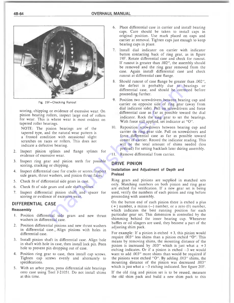
Fig. 19F—Checking Runout
scoring, ch ip p in g o r evidence o f excessive w ear. On
p in io n b earin g rollers, inspect large end o f rollers
fo r w ear. T his is w here w ear is m ost evident on
tap ered roller bearings.
N O T E : T he p in io n b earings are o f the
ta p ered type, and the n a tu ra l w ear p a tte rn is
a frosted co n d itio n w ith occasional slight
scratches on races o r rollers. T his does not
in d icate a defective b earing.
2.
Inspect p in io n splines and flange splines for
evidence o f excessive w ear.
3.
Inspect rin g g e a r and p inion teeth for possible
scoring, cracking or chipping.
4.
Inspect differential case for cracks or scores. Inspect
side gears, th ru st w ashers, and p in io n th ru st faces.
5.
Check fit o f differential side gears in case.
6.
Check fit o f side gears and axle sh aft splines.
7.
Inspect differential p in io n sh aft and spacer for
scoring or evidence o f excessive w ear.
DIFFERENTIAL CASE
Reassembly
1.
P osition differential side gears and new th ru st
w ashers in differential case.
2.
P osition d ifferential p in io n s and new th ru st w ashers
in differential case.. A lign pinions w ith holes in
differential case.
3.
Install p in io n sh a ft in differential case. A lign hole
in sh a ft w ith hole in case, th en install lock pin. Peen
hole to p rev en t p in d ro p p in g out o f case.
4.
Position rin g g e a r to case, then install cap screws.
T ig h ten cap screws evenly and altern ately to
specifications.
5.
W ith a n a rb o r press, press differential side b earings
onto case using Tool J-21051. D o not install shim s
at this tim e.
6.
Place differen tial case in c arrier and install b e arin g
caps. C are should be taken to install caps in
o rig in al position. Use m ark placed on caps and
ca rrie r at rem oval. T ighten caps ju st enough to keep
b e a rin g caps in place.
7.
Install d ial in d ica to r on carrie r w ith in d ic a to r
b u tto n co ntacting back o f ring gear, as in figure
19F. R o tate differential case and check fo r ru n o u t.
If ru n o u t is g re a te r th a n .002", the assem bly should
be rem oved and the rin g g ear rem oved from the
case. A g ain install differential case and check
ru n o u t at differential case flange.
8.
Should ru n o u t o f case flange be g reate r th a n .002",
th e d e fe c t is p ro b a b ly due to
b e a rin g s o r
d ifferential case, and should be corrected b efo re
p ro ceed in g fu rth er.
9.
P osition two screw drivers betw een b earin g cup an d
ca rrie r on opposite side o f rin g gear (aw ay fro m
dial in d ic a to r side). Pull on screw drivers and force
d ifferential case as fa r as possible tow ard the d ial
in d icato r. Rock the rin g g ear to set the bearings.
W ith force still applied, set in d icato r at "O " .
10.
R eposition screw drivers betw een b earin g cup and
c a rrie r on rin g g e a r side. Pull on screw drivers an d
force differen tial case as fa r as possible tow ard
cen ter o f carrier. R ecord the in d icato r reading. T his
will be the total am o u n t o f shim s needed (less
p relo ad ) fo r setting backlash later d u rin g assem bly.
11.
R em ove d ifferential from carrier.
DRIVE PINION
Installation and Adjustment of Depth and
Preload
R ing gears an d p in io n s are supplied in m atched sets
only. M atch in g nu m b ers on both p in io n and ring g ear
are etched fo r verification. If a new g ear set is b eing
used, verify the n u m b ers o f each p in io n and ring b efore
p ro ceed in g w ith assem bly.
O n the b u tto n end o f each p in io n there is etched a plus
( + ) n u m b er, a m inus (—) n u m b er, or a zero (0) n um ber,
w hich indicates the best ru n n in g position for each
p a rtic u la r g ear set. T his d im en sio n is controlled by the
sh im m in g b e h in d the in n e r b earin g cup. W henever
baffles o r oil slingers are used, they becom e a p a rt o f the
ad ju stin g shim pack.
F o r exam ple: If a p in io n is etched + 3, this p in io n w ould
re q u ire .003" less shim s th a n a p in io n etched " O " . T his
m eans by rem oving shim s, the m o u n tin g distance o f the
p in io n is increased by .003" w hich is ju st w hat a + 3
etch in g indicates. O r if a p in io n is etched —3 we w ould
w a n t to add .003" m ore shim s th a n w ould be req u ired if
the p in io n s w ere etched " O " . By ad d in g .003" shim s, the
m o u n tin g distance o f the p in io n was decreased .003"
w hich is ju st w h at a —3 etching indicated. See figure 20F.
If the old rin g an d p in io n set is to be reused, m easure
the old shim pack an d build a new shim pack to this
Summary of Contents for 1977 10 Series
Page 1: ......
Page 2: ......
Page 4: ......
Page 6: ......
Page 42: ......
Page 65: ...STEERING 3B 23 Fig 3B 65 M easure Back and Remark Housing Fig 3B 67 Tighten Lock Nut...
Page 86: ...4B 14 OVERHAUL MANUAL Fig 4B 28 Gear Teeth C ontact Pattern Check...
Page 125: ...REAR AXLE DIFFERENTIAL 4B 53 Fig 18E Gear Teeth Contact Pattern Check...
Page 156: ......
Page 164: ...4C 8 OVERHAUL MANUAL Fig 4C 12 Gear Tooth Pattern Contact Pattern...
Page 166: ......
Page 194: ......
Page 284: ......
Page 320: ......
Page 322: ...400 7A 2 OVERHAUL MANUAL Fig 7A 1C Side Cross Section Typical...
Page 444: ...7B 64 OVERHAUL MANUAL Fig 7B 11S M od el 2 03 Transfer Case Exploded V iew...
Page 458: ......
Page 466: ......
Page 467: ......
Page 468: ......