


REAR AXLE DIFFERENTIAL
4B-57
tools J-8092 and b e a rin g in staller J-24383 as shown
in figure 7F.
9.
Install b earin g on o p p o site side in the sam e
m anner. Be sure to su p p o rt differen tial case on pilot
plug J-8107-3.
SHIM REQUIREMENTS—GAUGING
PROCEDURES
Side Bearing Shims
1.
W ith the pinion rem oved from the carrier, place
the b earin g cups over the side bearings, and install
the differential case into the carrie r.
2.
Place the shim w hich w as o rig in a lly installed on the
ring gear side into its o rig in a l position.
3.
Install the b earing caps lightly in th eir m ark ed
positions. T ighten the caps ju s t en o u g h to keep the
bearings in place.
4.
M o u n t a dial in d icato r on the c a rrie r w ith the tip o f
the in d icato r on the back face o f the rin g gear.
5.
Position two screw drivers betw een the b earin g shim
an d carrier on the rin g g e a r side o f the case. Pull
on the screw drivers an d force the d ifferential case
as fa r as possible away fro m the d ial indicator.
6.
W ith force still applied, set the in d icato r dial to
"z e ro " , being sure the p ro b e is still in contact w ith
the rin g gear.
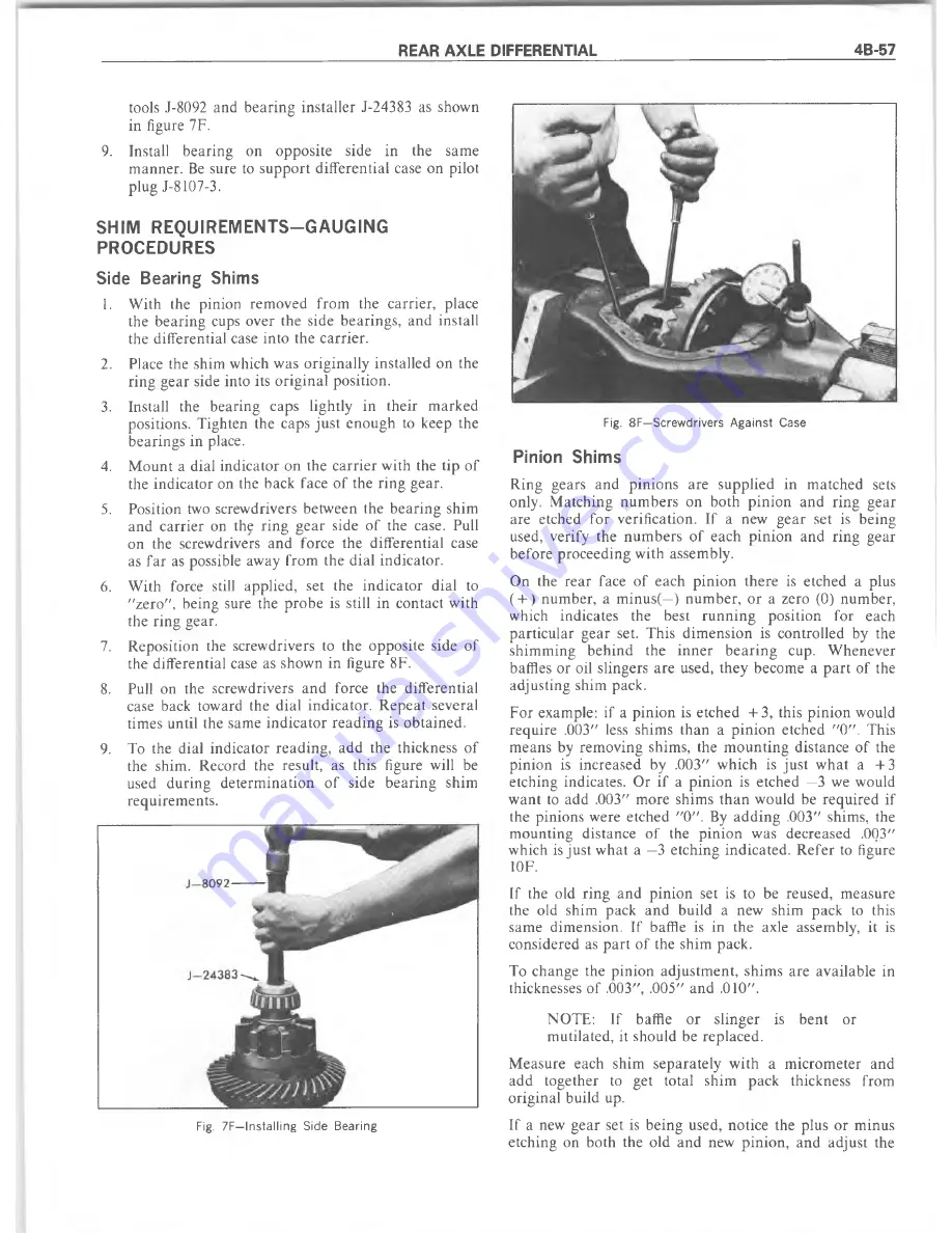
7.
R eposition the screw drivers to the opposite side o f
the differential case as show n in figure 8F.
8.
Pull on the screw drivers an d force the differential
case back tow ard the d ial in d ica to r. R ep eat several
tim es until the sam e in d ic a to r re a d in g is ob tain ed .
9.
To the dial in d icato r re a d in g , add the thickness o f
the shim . R ecord the result, as this figure will be
used d u rin g d ete rm in a tio n o f side b earin g shim
requirem ents.
Fig. 7F—Installing Side Bearing
Fig. 8F—Screwdrivers A g a in st Case
Pinion Shims
R ing gears and p in io n s are supplied in m atched sets
only. M atching n u m b ers on both p in io n an d rin g gear
are etched fo r verification. If a new g ea r set is being
used, verify the n u m b ers o f each p in io n an d ring gear
b efore p roceeding w ith assem bly.
On the re a r face o f each p in io n th ere is etched a plus
( + ) num ber, a m inus(—) n u m b er, o r a zero (0) n um ber,
w hich indicates the best ru n n in g position for each
p a rticu lar gear set. T his d im en sio n is controlled by the
shim m ing b ehind the in n e r b e a rin g cup. W henever
baffles or oil slingers are used, th ey becom e a p a rt o f the
adjusting shim pack.
F or exam ple: if a p in io n is etched + 3 , this p in io n would
req u ire .003" less shim s th a n a p in io n etched " 0 " . T his
m eans by rem oving shim s, the m o u n tin g distance o f the
p in io n is increased by .003" w hich is ju st w h at a + 3
etching indicates. O r if a p in io n is etched —3 we would
w ant to add .003" m ore shim s th a n w ould be req u ired if
the pinions were etched "0 " . By a d d in g .003" shim s, the
m ounting distance o f the p in io n w as d ecreased .003"
w hich is ju st w hat a —3 etching in d icated . R e fe r to figure
10F.
If the old rin g and p in io n set is to be reused, m easure
the old shim pack an d build a new shim pack to this
sam e dim ension. If baffle is in the axle assem bly, it is
considered as p a rt o f the shim pack.
To change the p in io n ad ju stm en t, shim s are available in
thicknesses o f .003", .005" and .010".
N O T E :
If baffle o r slin g er is ben t or
m utilated, it should be replaced.
M easure each shim sep arately w ith a m icro m eter and
add together to get total shim pack thickness from
o rig in al build up.
If a new g ear set is being used, notice the plus or m inus
etching on both the old and new p in io n , an d adjust the
Summary of Contents for 1977 10 Series
Page 1: ......
Page 2: ......
Page 4: ......
Page 6: ......
Page 42: ......
Page 65: ...STEERING 3B 23 Fig 3B 65 M easure Back and Remark Housing Fig 3B 67 Tighten Lock Nut...
Page 86: ...4B 14 OVERHAUL MANUAL Fig 4B 28 Gear Teeth C ontact Pattern Check...
Page 125: ...REAR AXLE DIFFERENTIAL 4B 53 Fig 18E Gear Teeth Contact Pattern Check...
Page 156: ......
Page 164: ...4C 8 OVERHAUL MANUAL Fig 4C 12 Gear Tooth Pattern Contact Pattern...
Page 166: ......
Page 194: ......
Page 284: ......
Page 320: ......
Page 322: ...400 7A 2 OVERHAUL MANUAL Fig 7A 1C Side Cross Section Typical...
Page 444: ...7B 64 OVERHAUL MANUAL Fig 7B 11S M od el 2 03 Transfer Case Exploded V iew...
Page 458: ......
Page 466: ......
Page 467: ......
Page 468: ......