


BRAKES
5-5
Inspecting Metal Parts
BA DLY D A M A G E D ITEM S, O R TH O SE W H IC H
W O U LD T A K E EX TEN SIV E W O R K O R T IM E TO
R E P A IR , SH O U LD BE R E PL A C E D . In case of doubt,
install new parts. Do not rely on the brake unit being
overhauled at an early or proper interval. New parts will
provide more satisfactory service, even if the brake unit is
allowed to go beyond the desired overhaul period.
Assembly
1. Be careful during the rebuild procedure that no grease
or mineral oil comes in contact with the rubber parts of the
power brake unit.
2. Lubricate power head parts, as outlined below, with
power brake silicone lubricant. This lubricant is provided in
the service repair kit.
Front Housing Group
1. Install a
new
vacuum check valve and a
new
grommet in front housing.
2. Place
new
front housing seal in housing so flat
surface of cup lies against bottom of depression in housing.
Power Piston Group
1. Lubricate the I.D. and O.D. of the "O" ring seal with
silicone lubricant and place on the air valve.
2. Wipe a thin film of silicone lubricant on the large and
small O.D. of the floating control valve.
3. If the floating control valve needs replacement, it will
be necessary to replace the complete air valve-push rod
assembly, since the floating control valve is a com ponent part
of this assembly and cannot be disassembled from the push
rod.
4. Place the air valve end of the air valve-push rod
assembly into the tube of the prim ary power piston. M anually
press the air valve-push rod assembly so that the floating
control valve bottom s on the tube section of the prim ary
power piston. Installer Tool J-23175 can be used to manually
press the floating control valve to its seat.
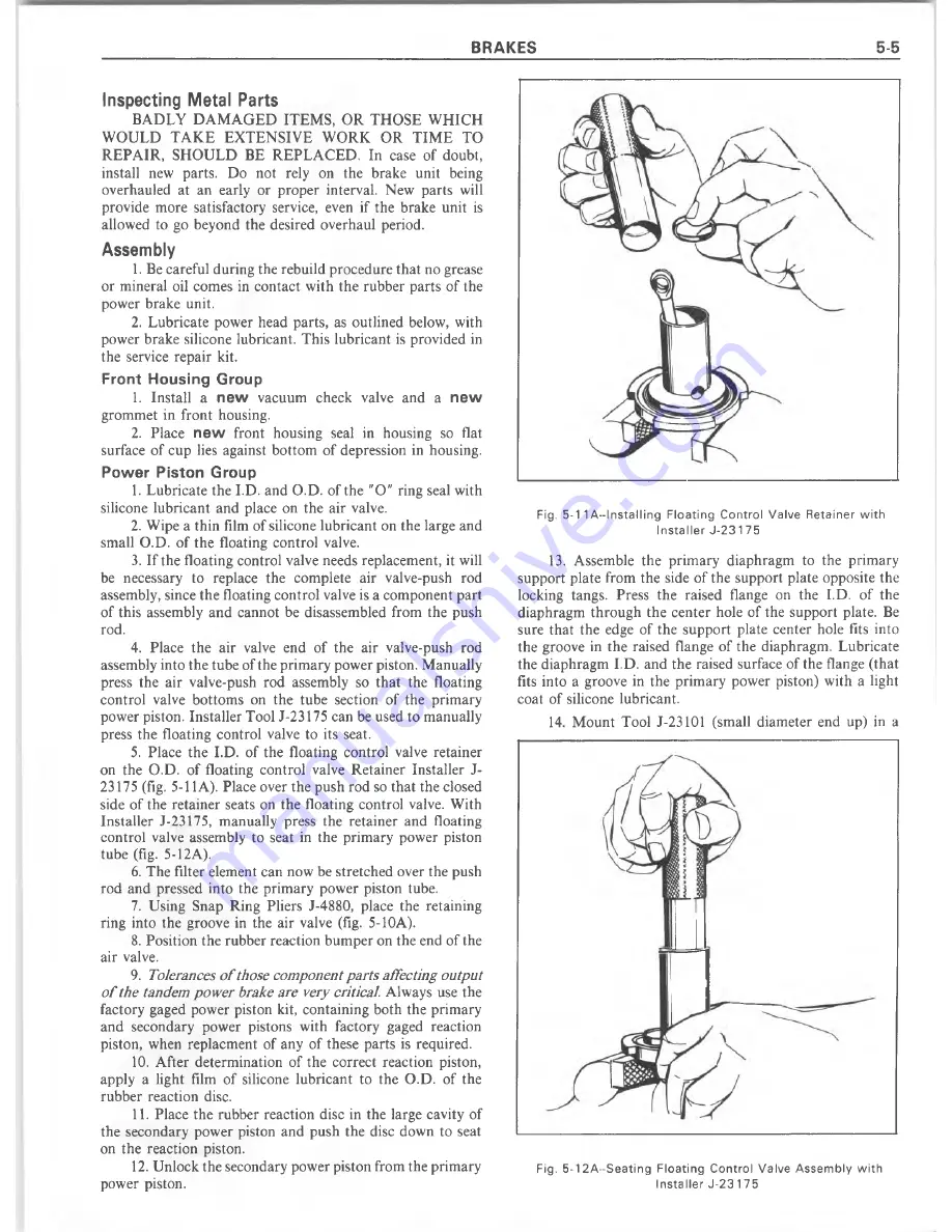
5. Place the I.D. of the floating control valve retainer
on the O.D. of floating control valve R etainer Installer J-
23175 (fig. 5-11 A). Place over the push rod so that the closed
side of the retainer seats on the floating control valve. W ith
Installer J-23175, m anually press the retainer and floating
control valve assembly to seat in the prim ary power piston
tube (fig. 5-12A).
6. The filter element can now be stretched over the push
rod and pressed into the prim ary power piston tube.
7. Using Snap Ring Pliers J-488Q, place the retaining
ring into the groove in the air valve (fig. 5-10A).
8. Position the rubber reaction bum per on the end of the
air valve.
9.
Tolerances o f those component parts affecting output
o f the tandem power brake are very critical.
Always use the
factory gaged power piston kit, containing both the prim ary
and secondary power pistons with factory gaged reaction
piston, when replacment of any of these parts is required.
10. After determ ination of the correct reaction piston,
apply a light film of silicone lubricant to the O.D. of the
rubber reaction disc.
11. Place the rubber reaction disc in the large cavity of
the secondary power piston and push the disc down to seat
on the reaction piston.
12. Unlock the secondary power piston from the prim ary
power piston.
Fig. 5-1 1 A —I nsta llin g F lo a tin g C o n tro l V a lve R e ta in e r w ith
In s ta lle r J -2 3 1 75
13.
Assemble the prim ary diaphragm to the prim ary
support plate from the side of the support plate opposite the
locking tangs. Press the raised flange on the I.D. of the
diaphragm through the center hole of the support plate. Be
sure that the edge of the support plate center hole fits into
the groove in the raised flange of the diaphragm. Lubricate
the diaphragm I.D. and the raised surface of the flange (that
fits into a groove in the prim ary power piston) with a light
coat of silicone lubricant.
14. M ount Tool J-2 3 101 (small diam eter end up) in a
Fig. 5 -1 2 A - S e a tin g F lo a tin g C o n tro l V a lv e A s s e m b ly w ith
In s ta lle r J-2 3 1 75
Summary of Contents for 1977 10 Series
Page 1: ......
Page 2: ......
Page 4: ......
Page 6: ......
Page 42: ......
Page 65: ...STEERING 3B 23 Fig 3B 65 M easure Back and Remark Housing Fig 3B 67 Tighten Lock Nut...
Page 86: ...4B 14 OVERHAUL MANUAL Fig 4B 28 Gear Teeth C ontact Pattern Check...
Page 125: ...REAR AXLE DIFFERENTIAL 4B 53 Fig 18E Gear Teeth Contact Pattern Check...
Page 156: ......
Page 164: ...4C 8 OVERHAUL MANUAL Fig 4C 12 Gear Tooth Pattern Contact Pattern...
Page 166: ......
Page 194: ......
Page 284: ......
Page 320: ......
Page 322: ...400 7A 2 OVERHAUL MANUAL Fig 7A 1C Side Cross Section Typical...
Page 444: ...7B 64 OVERHAUL MANUAL Fig 7B 11S M od el 2 03 Transfer Case Exploded V iew...
Page 458: ......
Page 466: ......
Page 467: ......
Page 468: ......