REAR SUSPENSION AND DRIVE LINE 4-41
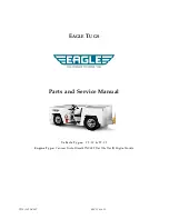
F ig . 7 6 — 18,500 and 2 3 ,0 0 0 lb . Eaton S in g le Speed A x le (1 8 ,5 0 0 lb . A x le Shown)
1. Flange N u t
8 . A d ju s tin g S pacer
16. Side G e a r Thrust
22. Ring G e a r B o lt
2 ,. P in io n Flange
9. B earing C up - In n e r
W asher
23. B earing C ap
3. O i l Seal
10. Bearing C one - Inn er
17. Side G e a r
24. B earing C one
4 . P in io n Cage
11. D riv e P in io n
18. Case B o lt
25. A d ju s tin g N u t
5 . A d ju s tin g Shims
12. D iffe r e n tia l C a rrie r
19. P in io n Thrust
26. A d ju s tin g N u t
6. B earing C up - O u te r
13. B earing
W asher
Lock
7. B earing C one -
14. A x le S haft - R.H.
20. D iffe r e n tia l P in io n
27. A x le S h a ft - L.H .
O u te r
15. D iffe r e n tia l Case
21. Ring G e a r
The d riv e pinion assem bly and the d iffe re n tia l case
assem b ly a re mounted in the d iffe re n tia l c a r r ie r , and are
rem oved as p art o f the c a r r ie r when the c a r r ie r is r e
m oved fro m the axle housing.
The d iffe re n tia l is a conventional four pinion type with
rin g g e a r bolted to flanged half o f d iffe re n tia l case. D if
fe re n tia l case is a tw o -p iece type machined as a matched
assem bly, and must be replaced as such.
Thrust w ashers a re used between d iffe re n tia l side
ge a rs and case, and between d iffe re n tia l pinions and case.
Adjusting rings in the d iffe re n tia l bearin g b o re s of the
c a r r ie r p rovid e fo r adjustment o f d iffe re n tia l side b e a r
ing p re -lo a d and ring g e a r -d r iv e pinion backlash.
AXLE SHAFTS A N D H O U SIN G
A x le shafts a re fu ll-flo a tin g type, splined to d ifferen tia l
side g ea rs at inner ends and attached at flanged outer
ends to hubs by studs and nuts. Stud holes in each shaft
flange are ta p er-rea m ed to accom m odate sp lit tapered
dowels.
The banjo-type axle housing is on e-p iece design with
sprin g seats w elded in place. Brake flange p lates are
riv e te d to flan ges w elded on the axle housing tube. Outer
ends o f housing a re machined to accom m odate wheel
b earin gs and threads a re cut at extrem e outer ends fo r
installation o f w heel bearin g nuts.
CHEVROLET TRUCK SERVICE MANUAL
Summary of Contents for 10 Series 1970
Page 1: ......
Page 38: ...HEATER AND AIR CONDITIONING 1A 8 CHEVROLET TRUCK SERVICE MANUAL...
Page 57: ...HEATER AND AIR CONDITIONING 1A 27 Fig 35 Compressor M ountings CHEVROLET TRUCK SERVICE MANUAL...
Page 78: ......
Page 142: ...CHEVROLET TRUCK SERVICE MANUAL Fig 5 10 30 Series Truck Frame FRAME 2 4...
Page 145: ...CHEVROLET TRUCK SERVICE MANUAL FRAME 2 7...
Page 148: ......
Page 238: ......
Page 383: ...ENGINE FUEL 6M 19 F ig I t Engine Fuel S p ecial Tools CHEVROLET TRUCK SERVICE MANUAL...
Page 384: ......
Page 392: ......
Page 432: ...Fig 1 C lu tch Linkage Except P 2 0 4 0 Series...
Page 528: ...Fig 31 T yp ica l Power Steering Hose Routings...
Page 530: ......
Page 550: ......
Page 568: ...ELECTRICAL BODY AND CHASSIS 12 6 Fig 5 Rear Lighting Composite CHEVROLET TRUCK SERVICE MANUAL...
Page 628: ......
Page 640: ......
Page 649: ...SPECIFICATIONS 9 ENGINE SECTION 6 CHEVROLET TRUCK SERVICE MANUAL...
Page 671: ......