196
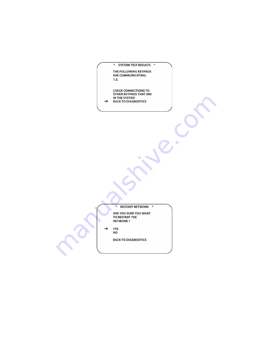
20 that are communicating properly will be shown on screen. If there are keypads in the system
that do not appear, check to be sure they are powered up from the WPS21 Power Hubs and that
they are properly connected via CAT5e to the AVH21 Hubs.
Figure 122 System Test Screen
To Run System Test:
1. In the Main Room, with the AVR21EN and video display ON, using the AVR21ENR1 remote,
press the
AVR Button [oval 5]
.
2. Press
the
MENU Button [oval 44]
. The
MAIN MENU
will appear.
3. Press
the
▼
/
▲
Navigation Button [oval 16]
to place the cursor next to
DIAGNOSTICS
.
Press the
Set Button [oval 18]
. The
DIAGNOSTICS
screen will appear.
4. With the cursor next to
RUN SYSTEM TEST
, press the
Set Button [oval 18]
. The
SYSTEM
TEST RESULTS
screen will appear. (
Figure 122
)
5. To return to
DIAGNOSTICS
, with the cursor positioned next to
BACK TO DIAGNOSTICS
,
press the
Set Button [oval 18]
.
6. To return to system mode, press the
Exit Button [oval 17]
.
Restart Network
In the unlikely event that the W.H.E.N. System should lock up, this sub-menu will unlock the
network and restart it. This will only restart the network and will not affect any configuration that
has been done to Zones, Groups, Cameras, Doors etc.
Figure 123 Restart Network
To Restart the Network:
1. In the Main Room, with the AVR21EN and video display ON, using the AVR21ENR1 remote,
press the
AVR Button [oval 5]
.
2. Press
the
MENU Button [oval 44]
. The
MAIN MENU
will appear.
3. Press
the
▼
/
▲
Navigation Button [oval 16]
to place the cursor next to
DIAGNOSTICS
.
Press the
Set Button [oval 18]
. The
DIAGNOSTICS
screen will appear.
Summary of Contents for AVR21EN
Page 1: ...1 INSTALLATION INSTRUCTIONS...
Page 41: ...41 AVR21ENR1 FUNCTION LIST Figure 8 AVR21ENR1 Button Locations...
Page 156: ...156 KP21R ZONE REMOTE FUNCTION LIST Figure 84 KP21R Button Locations...
Page 159: ...159 Figure 86 Typical Three Zone System...
Page 161: ...161 Figure 87 Typical Hub System...
Page 164: ...164 Figure 90 Multiple Hub Power Connections...


