


6 SEQUENCE INSTRUCTIONS
6.3 Output Instructions
121
6
Setting devices (excluding annunciator)
SET
The status of the device specified by (d) changes as follows when the execution command turns ON.
• Bit device: Turns the coils and contacts ON.
• Bit specification of word device: Set the specified bit to 1.
Setting data
■
Descriptions, ranges, and data types
■
Applicable devices
*1 When using F, refer to
*2 T, ST, C cannot be used.
*3 Only the FX5 intelligent function module can be used.
Processing details
• The status of the specified device changes as follows when the execution command turns ON.
• A device that is turned ON is held on even if the execution command turns OFF. Devices that are turned ON by the SET
instruction can be turned OFF by the RST instruction.
• When the execution command is OFF, the device status does not change.
Ladder diagram
Structured text
ENO:=SET(EN,d);
FBD/LD
Operand
Remarks
Range
Data type
Data type (label)
(d)
Bit device number/ Bit specification of word device to be
set (turns ON)
Bit
ANY_BOOL
EN
Execution condition
Bit
BOOL
ENO
Execution result
Bit
BOOL
Operand
Bit
Word
Double word Indirect
specification
Constant
Others
(DY)
X, Y, M, L, SM,
F, B, SB, S
T, ST, C, D, W,
SD, SW, R
U
\G
Z
LC
LZ
K, H
E
$
(d)
Device
Device status
Bit devices
Turns coils and contacts ON.
Bit specification of word device
Sets the specified bit to 1.
(d)
EN
ENO
d
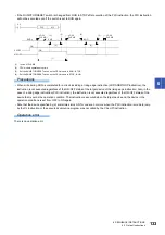
SET
Y10
RST
Y10
X5
X7
X5 OFF
X7 OFF
Y10 OFF
ON
ON
ON
Summary of Contents for MELSEC iQ-F FX5
Page 1: ...MELSEC iQ F FX5 Programming Manual Instructions Standard Functions Function Blocks ...
Page 2: ......
Page 17: ...15 CONTENTS ...
Page 24: ...22 MEMO ...
Page 1050: ...1048 26 TIME DATA FUNCTIONS 26 4 Division MEMO ...
Page 1068: ...1066 29 COUNTER FUNCTION BLOCKS 29 4 Counter Function Block Operation error There is no error ...
Page 1107: ...I 1105 MEMO ...
Page 1111: ......


