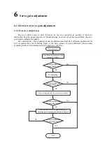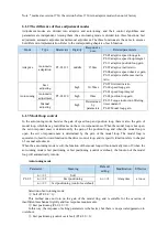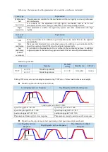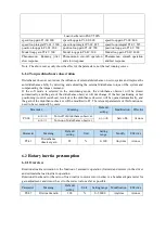
background image


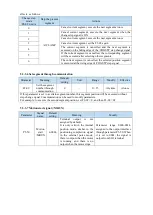
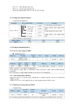
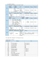
1.  No  terminal  output  signal  is  assigned  by  default.  The  parameter  range  is  0000-0014,  which  is 

allocated to other output terminals through parameter P5-40. 

2. When the speed of the servo motor is higher than the set value of P5-03, the signal that the servo is 
rotating is considered. 


2. Related parameters 

Parameter   

Meaning   

Default 

value 

Unit   

Range   

Modify   

Effective   

P5-03 

Rotating detection 

speed /TGON 

50 

rpm 

0

10000 

Anytime   

At once 

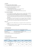
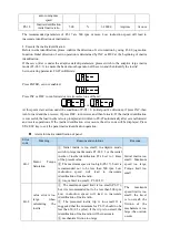
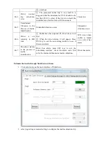
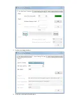
If  the  speed  of  the  servo  motor  exceeds  the  set  value  of  P5-03,  it  is  judged  that  the  servo  motor  is 
rotating and the output of the rotation detection (/TGON) signal. 

Note: Rotation detection has a hysteresis of 10 rpm. 

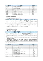
3. Hysteresis 

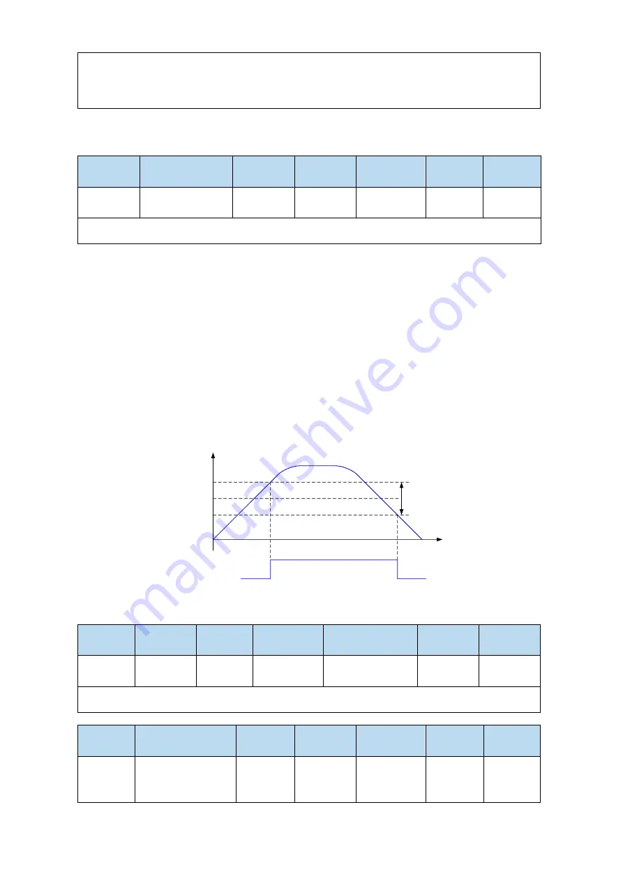
Hysteresis is set up to prevent the system from repeatedly acting and oscillating when the parameters 

fluctuate  up  and  down  in  a  certain  value.  Once  the  hysteresis  value  is  set,  there  will  be  a  fixed  ring 

width.  Then  only  when  the  parameter  must  be  greater  than  a  certain  value  can  the  action  be  taken. 

When  the  parameter  is  smaller  than  another  value,  the  action  will  be  released.  The  ring  width 

determines the interval time of the action. The action of small ring width is sensitive and frequent, and 

the action of large ring width is slow.   

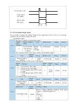
It should be noted that the rotation detection speed (P5-03), the same speed detection speed (P5-04), the 

arrival detection speed (P5-05), all contain 10 rpm hysteresis. For example, the rotation detection speed 

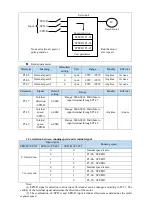
P5-03 is set to 50, and the rotation detection/TGON output port is SO3. 

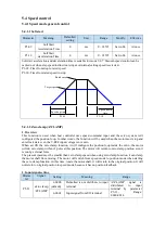
rpm

/TGON

60rpm

50rpm
40rpm

Ring 

width

ON

OFF

OFF


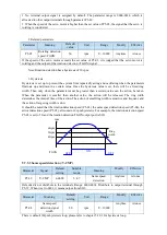
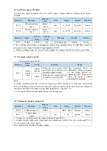
5.7.5.3 Same speed detection (/V-CMP) 

Parameter   

Signal   

Default 

setting 

Suitable 

mode 

Meaning   

Modify   

Effective   

P5-39 

/V-CMP 

n.0000 

3, 4, 7 

Same speed 

detection 

Anytime 

At once 

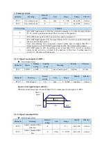
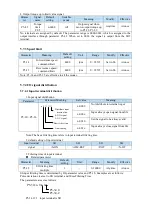
Defaulted is not distribute to the terminals. Range: 0000-0014. Distribute to output terminal through 
P5-39. When it set to 0002, it means output from SO2. 
 

Parameter   

Meaning   

Default 

setting 

Unit   

Range   

Modify   

Effective   

P5-04 

Same speed 

detection signal 

width 

50 

rpm 

0

10000 

Anytime   

At once 

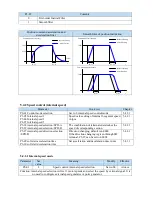
There is default 10rpm hysteresis loop, please refer to chapter 5-12-3 for hysteresis loop. 

Содержание DS5L1 Series

Страница 1: ...DS5L1 series servo driver User manual WUXI XINJE ELECTRIC CO LTD Data No SC5 05 20200929 1 0 ...

Страница 2: ......

Страница 3: ...eclaration of liability Although the contents of the manual have been carefully checked errors are inevitable and we cannot guarantee complete consistency We will often check the contents of the manual and make corrections in the subsequent versions We welcome your valuable comments If there is any change to the contents introduced in the manual please understand without further notice Contact inf...

Страница 4: ...touch the conductive part of the product directly which may cause misoperation and malfunction Cautions for wiring 1 Please connect AC power to LN or L1 L2 L3 or R S T on the dedicated power terminal of the driver Do not connect the output terminals U V W of the driver to the three phase power supply 2 Please connect the ground wire correctly Poor grounding may cause electric shock Please use 2mm2...

Страница 5: ... control it once in 2 minutes Maintenance and inspection 1 Do not touch the inside of servo driver and servo motor otherwise it may cause electric shock 2 When the power is started it is forbidden to remove the driver panel otherwise it may cause electric shock 3 Within 10 minutes of power off the terminal should not be contacted Otherwise the residual voltage may cause electric shock Wiring atten...

Страница 6: ......

Страница 7: ...on cautions 14 2 2 3 Installation environment 15 2 3 SERVO CABLE INSTALLATION 16 2 3 1 Cable selection 16 2 3 2 Xinje cable specification 17 2 4 SERVO DRIVER DIMENSION 19 2 5 SERVO MOTOR DIMENSION 20 3 SERVO SYSTEM WIRING 22 3 1 MAIN CIRCUIT WIRING 23 3 1 1 Servo driver terminal arrangement 23 3 1 2 Main circuit terminal 23 3 1 3 CN0 CN2 terminal 24 3 1 4 Communication port 25 3 2 CLASSIFICATION A...

Страница 8: ...protection 76 5 7 2 Torque limit 77 5 7 3 Speed limit 78 5 7 4 I O signal distribution 78 5 7 5 Output terminal function 79 5 7 6 Input terminal function 84 5 7 7 Time limit curve of overload protection 85 6 SERVO GAIN ADJUSTMENT 87 6 1 OVERVIEW OF SERVO GAIN ADJUSTMENT 87 6 1 1 Overview and process 87 6 1 2 The difference of these adjustment modes 88 6 1 3 Model loop control 88 6 1 4 Torque distu...

Страница 9: ...2 Vibration 120 6 8 3 Noise 120 7 ALARM 121 7 1 ALARM CODE LIST 121 7 2 ANALYSIS OF ALARM TYPES 123 8 APPENDIX 133 APPENDIX 1 GROUP P PARAMETERS 133 APPENDIX 2 UX XX MONITORING PARAMETERS 147 APPENDIX 3 FX XX AUXILIARY FUNCTION PARAMETERS 150 APPENDIX 4 MODBUS ADDRESS LIST 150 APPENDIX 5 Q A 155 APPENDIX 6 GENERAL DEBUGGING STEPS 157 APPENDIX 7 APPLICATION EXAMPLE 158 APPENDIX 8 SERVO GENERAL MODE...

Страница 10: ...mal if it can be turned smoothly by hand Servo motors with brakes however cannot be turned manually Is there any damage Check the overall appearance and check for damage or scratches that may have occurred during shipping Are there any loose screws Check screws for looseness using a screwdrive Is the motor code the same with the code in drive Check the motor code marked on the nameplates of the se...

Страница 11: ...er Display Rated output power 0P1 100W 0P2 200W 0P4 400W 0P7 750W Display Product name DS5 Servo driver Display Product series Display Rated input voltage 2 AC 220V L1 Compact model 1 1 2 Description of each part RS232 port CN0 pulse direction I O signal CN2 driver encoder interface Power supply Regenerative resistance Motor wiring ...

Страница 12: ...me MS5S 80 ST E C S 02430 B Z 2 0P7 S01 Name Rated power KW 0P2 0 2 0P4 0 4 0P7 0 75 Name Voltage level 2 220V 4 380V Name Power off brake Empty without Z with Name Shaft A No key B With key Name Inertia MS5S Low inertia MS5G Middle inertia MS5H High inertia Name Seat number 60 60 seat 80 80 seat Name Product name ST Sine drive motor Name Encoder type C Magnetic encoder T Photoelectric encoder Nam...

Страница 13: ...hole Display Power loss brake Z Empty With brake No brake Display 1 2 D Standard 1 Standard 2 Customized machine Display 2 4 220V 380V Display Rated output 0P1 0P2 100W 200W 0P4 0P7 400W 750W Display Base no 40 60 80 40 flange 60 flange 80 flange Symbol C T Magnetic Encoder Photoelectric encoder Product name Connector Encoder Power supply Note At present only the combination of CS CM TL and T is s...

Страница 14: ...isplay Length M Display Plug type P 4 core amp plug W 6 core waterproof small aviation plug Display Cable type CM Normal CMT High flexibility Display Cable type L 4 core small aviation plug XL 4 core medium aviation plug CM P 07 M 03 Display Diameter mm 07 0 75 15 1 5 25 2 5 60 6 03 3 05 5 08 8 M Magnetic encoder Empty Optical encoder D O terminal Brake cable explanation For 80 and below flange mo...

Страница 15: ... contains a 3 6V 2 7Ah large capacity battery and has the function of replacing batteries when power cut The using life is more than two years Please refer to chapter 5 6 2 change battery Power cable 1 Pin definition of power cable on servo driver side Connector appearance Pin definition Color Definition Brown U Black V Blue W Yellow green PE Connector pins Pin definition Suitable model No Definit...

Страница 16: ...returns to the servo amplifier side which is called regenerative power The regenerated power is absorbed by charging the smooth capacitor of the servo amplifier After exceeding the rechargeable energy the regenerative resistance is used to consume the regenerative power The servo motor driven by regenerative generator mode is as follows The deceleration stop period during acceleration and decelera...

Страница 17: ... 20P1 PTA 50Ω 50Ω 100Ω Above 200W DS5L1 20P2 PTA DS5L1 20P4 PTA 40Ω 40Ω 100Ω Above 500W DS5L1 20P7 PTA Note 1 The smaller the resistance is the faster the discharge will be but the smaller the resistance is the easier the breakdown resistance will be Therefore please close to the the lower limit but not be less than the lower limit when choosing the type 2 When wiring please use high temperature f...

Страница 18: ...re 20 60 Storage humidity 20 90 RH no condensation 2 1 3 Installation standard Be sure to comply with the installation standard in the control cabinet shown in the figure below This standard is applicable to the situation where multiple servo drivers are installed side by side in the control cabinet hereinafter referred to as when installed side by side Servo Drive Orientation Install the servo dr...

Страница 19: ...stallation instructions carefully CAUTION 1 The end of the motor shaft is coated with antirust Before installing carefully remove all of the paint using a cloth moistened with paint thinner 2 Avoid getting thinner on other parts of the servo motor 2 2 1 Environment condition When used in places with water droplets or oil droplets the protection effect can be achieved through the treatment of motor...

Страница 20: ...pling or similar methods are used When the pulley is dismantled the pulley mover is used to prevent the bearing from being strongly impacted by the load To ensure safety protective covers or similar devices such as pulleys installed on shaft are installed in the rotating area Centering When installing the servo motor make it conform to the centering accuracy requirement shown in the picture below ...

Страница 21: ...he connector from the side of the main circuit cable of the servo motor first and the grounding wire of the main cable must be connected reliably If one side of the encoder cable is connected first the encoder may fail due to the potential difference between PE When wiring please make sure that the pins are arranged correctly Connectors are made of resin Do not apply shock to avoid damaging the co...

Страница 22: ...rrent of the motor For example the maximum current of the motor is 60A and the wire diameter of 6mm is selected In case of interference it is necessary to separate strong and weak current It is recommended to separate power cable from encoder cable and signal cable Ensure the correct grounding of servo driver and servo motor The grounding resistance is not more than 4Ω and the grounding depth is m...

Страница 23: ...equipment The motor is properly grounded High current equipment shall be grounded separately Reasonable wiring Such as separation of strong and weak current cables Use metal shielding layer to shield add magnetic ring to the encoder cable to resist interference 4 Low high temperature Select cables special cables that meet the use conditions 2 3 2 Xinje cable specification 1 Material composition of...

Страница 24: ...inary temperature resistance 20 80 20 80 Encoder cable withstand voltage 1000V min 1000V min Power cable withstand voltage 3000V min 3000V min Mobile installation Bending radius Travel 10m 7 5 D Travel 10m 10 D Travel 10m 7 5 D Travel 10m 10 D Bending resistance times Travel 10m 1 million times Travel 10m 2 million times Travel 10m 3 million times Travel 10m 5 million times Fixed installation Bend...

Страница 25: ...2 4 Servo driver dimension DS5L1 20P1 PTA DS5L1 20P2 PTA DS5L1 20P4 PTA Unit mm AC220V 400W CN3 CN0 CN2 CHARGE DS5L1 20P7 PTA Unit mm CN2 CHARGE CN0 CN3 AC220V 750W ...

Страница 26: ...stallation dimensions Unit mm a60 7 0 4 5 5 11 0 0 1 5 0 0 03 M5深 8 50h7 30 0 5 14h6 2 LA 83 20 2 Motor model LA 1 Inertia level Series Normal With brake MS5S 60ST C 00630 20P2 S01 S02 79 114 Low inertia MS5 series MS5S 60ST C 01330 20P4 S01 S02 99 134 MS5H 60ST C 00630 20P2 S01 S02 91 126 High inertia MS5H 60ST C 01330 20P4 S01 S02 111 146 MS 60ST T01330 20P4 D01 145 189 MS6S 60C 301B 1 20P4 107 ...

Страница 27: ...a MS5H 80ST C 03230 21P0 S01 S02 140 177 MS 80ST T02430 20P7 150 199 MS 80ST T03520 20P7 179 219 MS6S 80C 30B 1 20P7 117 150 Low inertia MS6 series MS6S 80C 20B 1 20P7 127 160 MS6H 80C 30B 1 20P7 124 157 High inertia MS6H 80C 20B 1 20P7 149 182 130 series motor installation dimensions Unit mm a130 1 4 5 4 9 LA 2 5 LB 57 0 5 40 2 5 22h6 110h7 18 5 0 0 1 6 0 0 02 M 6 深 1 5 Motor model LA 1 LB Inerti...

Страница 28: ...lti stranded wire and the multi core stranded integral shielding wire 3 For wiring length the longest instruction input wire is 3m and the longest PG feedback wire is 20m 4 Even if the power supply is off there may still be a high voltage in the servo unit Please do not touch the power terminal temporarily 10 minutes 5 Do not turn ON OFF power frequently When the ON or OFF power supply needs to be...

Страница 29: ... circuit Single phase AC 200 240V 50 60Hz Vacant terminal U V W PE Motor terminals Connect the motor Note the ground wire is on the terminal please check it before power on P C External regenerative resistor Connect regenerative resistor between P and C P0 25 power value P0 26 resistor value RS232 port CN0 pulse direction I O signal interface CN2 encoder interface Power supply Regenerative resista...

Страница 30: ... P and D P0 25 power value P0 26 resistor value 3 1 3 CN0 CN2 terminal 3 1 3 1 CN0 terminal P P 24 D P 24 SI1 SI2 SI3 24V SO1 SO2 SO3 COM CN0 terminal explanation Name Explanation Name Explanation P Pulse input PUL SI3 Input terminal 3 P 24 Open collector connection 24V Input 24V D Direction input DIR SO1 Output terminal 1 D 24 Open collector connection SO2 Output terminal 2 SI1 Input terminal 1 S...

Страница 31: ...ng P input signal D input signal Chapter P0 10 xxx 0 CW CCW dual pulse mode CW CCW 5 3 2 2 1 AB phase mode A phase B phase 2 Pulse direction mode pulse direction Collector open circuit type 24V voltage input signal is P 24V D 24V The wiring diagram of P D CW CCW and AB phase interface circuit is as follows Open collector 24V voltage PLC CNC and SCM servo driver Note 1 The power supply voltage rang...

Страница 32: ...wer supply is 24V Relay type power supply is 24V Upper device servo driver SI 24V COM2 Y2 0V 24V R 3 3KΩ Upper device servo driver R 3 3KΩ 24V 0V Y2 COM2 24V SI Note The maximum allowable voltage and current capacity of collector open circuit output circuit are as follows Voltage DC 30V maximum Current DC 50mA maximum 3 2 3 SO output signal Type Output terminal Function Optocoupler output SO1 SO3 ...

Страница 33: ...Voltage DC 30V maximum Current SO1 DC 500mA maximum 400W and below servo can support SO others DC 50mA maximum ...

Страница 34: ... code Present speed Alarm clear state Parameter Monitor Auxiliary Alarm STA ESC switch Parametric setting Px xx The first X represents the group number and the last two X represents the parameter serial number under the group Monitor status Ux xx The first X represents the group number and the last two X represents the parameter number under the group Auxiliary function Fx xx The first X denotes t...

Страница 35: ...it rpm When the motor speed is higher than the rotating speed turn on the lamp Rotation detection speed P5 03 unit rpm P5 31 Zero clamp ZCLAMP When the zero clamp signal starts to operate turn on the light P5 43 Speed limit VLT When the speed exceeds the set value turn on the light when the torque is controlled Forward speed limit in torque control P3 16 reverse speed limit P3 17 2 Short code disp...

Страница 36: ...gher than the rotating speed turn on the lamp Rotation detection speed P5 03 unit rpm 2 Short code display contents Short code Display contents Standby status Servo OFF status The motor is in a non electrified state In operation Servo enabling state The motor is on line Need reset status Servo needs to be re energized Forbidden forward drive state P OT ON status Refer to Section 5 2 4 Forbidden re...

Страница 37: ...x0001 means S ON has input 0x0201 means S ON and SPD B has input U0 22 input signal status STA ESC INC DEC ENTER 11 12 13 14 15 16 17 18 19 20 Lighting means that the corresponding item has signal input Lighting means that the corresponding item has no signal input U0 22 input signal 2 distribution Segment code Description Segment code Description 11 C SEL control mode selection 12 ZCLAMP zero cla...

Страница 38: ...eady S RDY 6 Torque limit CLT 7 Speed limit detection VLT 8 Break lock BK 9 Warn WARN 10 Output near NEAR Note When reading through communication the binary numbers read from right to left correspond to the position of COIN_HD COIN 0 means that the position signal is not output 1 means that the position signal has output Example 0x0001 means COIN_HD has output 0x0201 means COIN_HD and NEAR has out...

Страница 39: ...ters in the driver 0021 Read the encoder motor parameters successfully but the parameter value is 0 please set P0 53 0031 Read encoder motor parameters successfully but damaged CRC check error please set P0 53 0042 Failed to read encoder motor parameters please set P0 53 4 4 Group F auxiliary function parameters 4 4 1 Group F0 Function code Description Function code Description F0 00 Alarm clear F...

Страница 40: ...encoder F1 02 Current Sampling Zero correction 1 Test run F1 01 Before entering the test run mode please confirm that the motor shaft is not connected to the machine When the servo driver is connected to the non original encoder or power cable it should first enter the test run mode to verify that the encoder terminal or power terminal is connected correctly Test run mainly checks the power cable ...

Страница 41: ...el which supports motion bus Set P0 03 2 F1 05 0 cancel enable enter bb status F1 05 1 forced enable servo is in RUN status Note 1 After power on again the forced enable set by F1 05 will fail 2 If it needs to enable when power on and still enable after re power on P0 03 should be set to 1 and P5 20 to n 0010 5 Reset turns of absolute encoder F1 06 Refer to chapter 5 7 5 4 5 Fault alarm handling W...

Страница 42: ...e decrease or shift after changing long press ENTER to confirm 8 END Note When the setting parameter exceeds the range that can be set the driver will not accept the setting value and the driver will report E 021 parameter setting exceeds the limit The parameter setting overrange usually occurs when the upper computer writes parameters to the driver through communication 4 7 Change motor code A se...

Страница 43: ...position instruction can be given by the combination of external pulse input the total number of internal position instructions and speed limit The position is controlled by the number of input pulses and the speed is controlled by the frequency of input pulses It is mainly used in the occasions requiring positioning control such as manipulator grinder engraving machine CNC machine etc Speed contr...

Страница 44: ...to other input terminal through P5 30 If the control mode needs to be switched through SI2 input signal P5 30 can be set to n 0002 0012 Refer to section 3 2 2 for hardware wiring details Parameter setting Signal C SEL terminal input status Signal C SEL terminal logic Control mode P5 30 n 0000 No need external terminal input Invalid The control mode set by P0 01 Refer to chapter 5 1 1 P5 30 n 000 S...

Страница 45: ...ect only when the servo is not enabled i e the panel is BB Related parameter parameter Meaning Default setting Unit Range Modify Take effect P3 18 JOG speed 100 1rpm 0 1000 Servo bb At once P3 18 is the speed for closed loop inching operation which only takes effect in two inching modes and the rest normal control modes are invalid 1 jog by panel Related parameter Function code Meaning Explanation...

Страница 46: ... enabling of F1 05 can take effect and the forced enabling fails after power on again F1 05 can write 1 to hex address 0x2105 through ModbusRTU protocol communication or set to 1 through the panel 2 Power on enable Parameter setting P0 03 1 default P5 20 n 0010 This setting mode can make the servo system in the enabling state as soon as it is powered on without external terminal control and the se...

Страница 47: ...top Stopping principle The servo driver is not enabled the servo motor is not powered and free deceleration to 0 The deceleration time is affected by mechanical inertia equipment friction etc The servo driver outputs the reverse braking torque and the motor decelerates rapidly to 0 Stopping features Advantages smooth deceleration small mechanical impact small mechanical impact Disadvantage slow de...

Страница 48: ...op and give the stop timeout alarm E 262 3 The so terminal of servo driver is equipped with holding brake function No matter P0 27 P0 29 0 or 2 it stops in deceleration mode 2 Stop mode in case of over travel The overtravel prevention function of servo unit refers to the safety function that the servo motor is forced to stop by inputting the signal of limit switch when the movable part of the mach...

Страница 49: ...nal and the braking torque is P3 32 when decelerating stop and the stop timeout also plays a role in the overtravel process 2 During position control when the motor is stopped by over travel signal there may be position deviation pulse To clear the position deviation pulse the clear signal CLR must be input If the servo unit still receives pulses they will accumulate until the servo unit gives an ...

Страница 50: ...e power off brake is 24V 2 If the holding brake current is more than 50mA please transfer it through the relay to prevent terminal burnt out due to excessive current 2 Software parameter settings For the servo motor with holding brake it is necessary to configure one SO terminal of servo driver as holding brake output BK function and determine the effective logic of SO terminal that is parameter P...

Страница 51: ...lag P5 07 holding brake open Note the setting made here is the time when TGON of rotation detection is invalid when the motor is stopped Abnormal state holding brake timing When the alarm power supply interruption occurs the motor quickly becomes non energized During the time from gravity or inertia to the brake action the machine will move To avoid this The conditions for the BK signal to turn fr...

Страница 52: ... axis is running downward When the external load drives the motor to rotate Related parameter Parameter Meaning Default setting Unit Setting range Modify Effective P0 24 Discharge resistance type selection version 3640 and before 0 built in 1 external Power protection mode of discharge resistance version 3700 and later 0 cumulative discharge time 1 average power mode 1 2 average power mode 2 0 0 1...

Страница 53: ...s per revolution to 5000 Electronic gear ratio set to 131072 5000 Max speed 600rpm Two circle radius ratio 2 1 Big circle run one rotation need 20000 pulses small circle run two rotations Max speed 1200rpm Two circle radius ratio 2 1 Big circle run one rotation need 10000 pulses small circle run two rotations 2 In the precise positioning the physical unit length corresponding to 1 command pulse is...

Страница 54: ...coder pulse Confirm the servo motor encoder accuracy 3 Set the command unit Determine the actual distance or angle corresponding to 1 pulse of the controller 4 Calculate the command pulses the load shaft rotates 1 circle Based on the determined command unit calculate the command quantity n of the load shaft rotating for 1 revolution 5 Calculate the pulses per rotation M Command pulse number of mot...

Страница 55: ...ion P0 11 P0 12 P0 11 6000 P0 12 0 P0 11 1200 P0 12 0 P0 11 7850 P0 12 0 Set electronic gear ratio P0 13 P0 14 P0 92 95 P0 13 131072 P0 14 6000 After reduction P0 13 8192 P0 14 375 P0 13 131072 P0 14 1200 After reduction P0 13 8192 P0 14 75 P0 13 131072 P0 14 7850 After reduction P0 13 65536 P0 14 3925 Conver to second gear ratio P0 92 5536 P0 93 6 P0 94 3925 P0 95 0 5 3 1 2 Positioning completion...

Страница 56: ...tion mode P5 01 is set to 3 the positioning completion holding COIN HD signal can be output When the COIN signal holds P5 02 time the COIN HD signal can be output 2 COIN signal output conditions According to the positioning completion detection mode set in P5 01 output positioning completion COIN signal The following is the precondition for positioning output and the output diagram P5 01 setting C...

Страница 57: ...default is 11 command units The following table is an example Number of command pulses required for one revolution of motor positioning completion width P5 00 The positioning completion width P5 00 changes proportionally with the number of command pulses required for one revolution of the motor The output of the positioning completion signal depends on the positioning completion width The smaller ...

Страница 58: ...ly with the number of command pulses required for one revolution of the motor The output of the positioning completion signal depends on the positioning completion width The smaller the width is the later the positioning completion signal output is but the signal output does not affect the actual operation state of the motor 10000 default 50 default 20000 100 5000 25 3000 15 2000 10 2 The approach...

Страница 59: ...Signal name Default setting Suitable mode Meaning Modify Effective P5 34 CLR n 0000 All Pulse deviation clear Anytime At once Parameter range n 0000 001A assigned to other input terminals by parameter P5 34 If it is necessary to input signal from SI2 P5 34 can be set to n 0002 0012 Refer to section 3 2 2 for hardware wiring details 1 CLR signal effectiveness parameter setting status Signal CLR ter...

Страница 60: ...se will not be detected Alarm E 100 Alarm E 100 0 Deviation pulse P0 23 P0 23 Normal control Normal control 5 3 1 7 Position command filter Related parameters Parameter Meaning Default setting Unit Range Change Effective P1 24 Position command acceleration and deceleration filtering time 0 0 1ms 0 65535 Servo OFF At once P1 25 Position command smoothing filtering time 0 0 1ms 0 65535 Servo OFF At ...

Страница 61: ...ignal Range 0000 0014 distributes to input terminal through P5 28 When it set to 0001 it means input signal from SI1 Mode 5 find origin point at forward direction P5 29 SPD B n 0000 Mode 3 internal speed selecting signal Range 0000 0014 distributes to input terminal through P5 29 When it set to 0001 it means input signal from SI1 Mode 5 find origin point at reverse direction Related parameter sett...

Страница 62: ... pulse mode 5 3 2 1 P0 10 pulse instruction form Set the pulse form 0 CW CCW 1 AB 2 P D 5 3 2 2 P0 11 Motor pulse numbers per rotation 1 P0 12 Motor pulse numbers per rotation 10000 P0 13 Electronic gear ratio numerator P0 14 Electronic gear ratio denominator P0 92 P0 93 32 bit electronic gear ratio numerator P0 94 P0 95 32 bit electronic gear ratio denominator Setting of command pulse number requ...

Страница 63: ...ffective P0 09 2 n x xx Low speed pulse command filter time F 4 167ns 0 F Servo bb Re power on P0 09 2 is pulse filter time It can enhance the anti interference ability of low speed pulses less than 200K When the input is less than 700K the maximum filtering time F is recommended When the input pulse frequency exceeds 1M the filtering time should not be more than 7 Parameter Meaning Default settin...

Страница 64: ...n mode including step change mode positioning mode and adjustment time Configuration of pulse displacement speed acceleration and deceleration time of each segment 5 3 3 3 P5 35 change step signal GHGSTP P5 32 pause present segment signal INHIBIT P5 31 jump present segment signal Z CLAMP Common terminal function assignment 5 3 3 4 5 3 1 4 5 3 3 5 P4 00 number of Z phase signal after leaving limit ...

Страница 65: ...for the motor to be positioned after outputing a position instruction in internal position mode It takes effect in all Step Changing modes Waiting mode 0 adjust time 0ms Waiting mode 0 adjust time 0ms P t t1 P5 00 Pulse offset COIN Signal status ON OFF After the drive output 1 segment position command it will wait for the completion of motor positioning and then start the next position command at ...

Страница 66: ...1 t2 t1 ON OFF t1 P4 16 t2 P4 23 1 If the CHGSTP signal is always on the servo unit will cycle the set position segment all the time 2 If the CHGSTP signal is set to off when executing a certain segment the servo will continue to complete the execution of that segment without the execution of the next segment 3 In this mode the step change signal CHGSTP is triggered at high level 4 When the servo ...

Страница 67: ...e shutdown the positioning is invalid 5 The adjustment time is not valid in this mode 2 Start at the rising edge of the signal sequential run all not recycling P CHGSTP Signal status ON OFF t1 t Take setting two segments as an example t1 p4 16 in the figure 1 The CHGSTP signal before the completion of a cycle will not be counted as shown in the second CHGSTP signal in the figure 2 In this mode the...

Страница 68: ...ioning completion and positioning approach signal are all effective 2 When the servo enable is off during a certain section of operation the motor stops according to the servo off shutdown mode After the shutdown the positioning is invalid 3 The adjustment time is valid in this mode 4 CHGSTP signal is invalid only in this mode 5 The segment number selection terminal can not only trigger the step c...

Страница 69: ...tion is invalid 5 Segment number selection terminal logic is voltage level valid Input high voltage level is valid input low voltage level is invalid The following input signal can switch the segment 1 to 3 or 1 to 16 Parameter Signal name Default setting Suitable mode Setting range Modify Effective P5 57 PREFA internal position segment 1 n 0000 5 Range 0000 0014 distribute to input terminal throu...

Страница 70: ...e reference origin with the speed of this segment 7 In absolute positioning mode if two consecutive segments speed are not zero but the pulse number is the same the servo motor will not run but the wait mode is effective 8 In the absolute positioning mode the number of rotations of the motor is limited and cannot be unlimited 9 At present there are only two kinds of velocity in the internal positi...

Страница 71: ... 0 or P4 08 P4 04 P4 08 8 P4 04 4 start Segment 1 Segment 2 Segment 3 Segment 4 1 P4 08 P4 04 P4 08 2 P4 04 4 Segment 1 Segment 2 Segment 3 Segment 4 start P4 03 1 1 P4 08 0 or P4 08 P4 04 P4 08 8 P4 04 4 start Segment 1 Segment 2 Segment 3 Segment 4 end 1 P4 08 P4 04 P4 08 2 P4 04 4 Segment 1 Segment 2 Segment 3 Segment 4 start When using skip current segment function the SI terminal assigned by ...

Страница 72: ...ough communication Parameter Meaning Default setting Unit Range Modify Effective F2 09 Set the segment number through communication 0 0 35 Anytime At once If this parameter is set to a certain segment number this segment position will be executed without step change signal Communication can be used to modify parameters For example to execute the second segment position set F2 09 0 and then F2 09 0...

Страница 73: ...ill be used when the motor must stop and enter lock state even the V REF input voltage is not zero When set ON the zero clamp function it will configure the position loop inside the servo the motor will do zero clamp within 1 pulse at this position The motor will return to zero clamp position even it is run by external force The present speed must be smaller than zero clamp speed when using zero c...

Страница 74: ...AMP signal is ON the setting speed is less than P3 13 switch to position control mode and servo is locked at this position At this time if setting speed is over P3 13 the motor will run again 5 4 1 3 Speed reach signal V RDY Related parameter Parameter Signal Default setting Suitable mode Meaning Modify Effective P5 51 V RDY n 0000 3 4 7 Speed reach signal Anytime At once Parameter Meaning Default...

Страница 75: ...tting of internal 3 segment speed in rpm 5 4 2 1 P5 28 internal speed selection SPD A P5 29 internal speed selection SPD B The combination of terminals determines the speed of corresponding section 5 4 2 1 P5 27 internal speed direction selection SPD D Direction changing default is n 0000 If the direction changing is given through SI2 terminal P5 27 can be set to n 0002 5 4 2 1 P3 09 soft start ac...

Страница 76: ...terminal through P5 29 1 Correlation between running speed and terminal signal Input signal Running speed SPD D P5 27 SPD A P5 28 SPD B P5 29 0 forward run 0 0 Internal speed is zero 0 1 P3 05 SPEED1 1 1 P3 06 SPEED2 1 0 P3 07 SPEED3 1 reverse run 0 0 Internal speed is zero 0 1 P3 05 SPEED1 1 1 P3 06 SPEED2 1 0 P3 07 SPEED3 Note 1 SPD D signal is direction control input SI terminal can be changed ...

Страница 77: ...0000 No need external terminal input Invalid P5 27 n 000 SI terminal no signal input P5 27 n 001 SI terminal has signal input P5 27 n 0010 No need external terminal input Valid P5 27 n 000 SI terminal has signal input P5 27 n 001 SI terminal no signal input 3 Running example 0 SPEED1 Stop SPEED2 SPEED3 SPEED1 SPEED2 SPEED3 Speed 1 Speed 2 Speed 3 stop Speed 1 Speed 2 Speed 3 Stop Speed up down is ...

Страница 78: ...antity The wiring is the same as position command Select CW CCW mode or direction pulse mode AB phase pulse mode 5 4 3 2 Pulse frequency command Pulse frequency command is the same as external pulse command position control refer to chapter 5 3 2 5 4 3 3 Command pulse frequency at rated speed Parameter Meaning Default setting Unit Range Modify Effective P0 15 command pulse frequency at rated speed...

Страница 79: ...ame Default setting Suitable mode Meaning Modify Effective P5 43 VLT n 0000 1 2 Speed limit detection Anytime At once By default no terminal is allocated the parameter range is 0000 0014 and is allocated to the output interface through parameter P5 43 When set to 0002 the signal is output from the SO2 terminal VLT signal is only valid in torque mode 5 5 2 Torque control internal setting Parameter ...

Страница 80: ...s used as incremental encoder Pararmeter Name setting Meaning Range P0 79 Absolute encoder battery undervolta ge alarm switch 0 Normally use absolute encoder and use battery to memorize position 0 2 1 default Use multi loop absolute encoder as incremental encoder and no longer remember position 2 Use as absolute encoder ignore the multi loop overflow alarm 5 6 2 Replace the battery When replacing ...

Страница 81: ...nect the power supply of the servo unit again 7 Make sure the error display disappears and the servo unit can operate normally 5 6 3 The upper limit of turns The upper limit of rotating cycles can be used for position control of gyroscopes such as turntables For example suppose there is a machine whose turntable moves only in one direction as shown in the figure below ...

Страница 82: ...tor speed is lower than P0 75 unit 1 rpm and the duration reaches the set value of P0 74 unit ms the current output torque U0 02 is greater than the internal positive torque limit of P3 38 and the internal reverse torque limit of P3 39 it will show the alarm E 165 blocking overtime Related parameters Parameter Meaning Default setting Unit Range Modify Effective P0 74 Blocking alarm time According ...

Страница 83: ...0 Anytime At once P3 31 Reverse external torque limit 300 0 300 Anytime At once The unit is the percent of motor rated torque the default value is 300 Parame ter Signal name Default setting Meaning Range Modif y Effecti ve P5 25 P CL n 0000 The necessary condition to use forward external torque limit Range 0000 0014 can be distributed to other input terminals through P5 25 Anyti me At once P5 26 N...

Страница 84: ...al distribution 1 Input signal distribution Parameter Parameter Meaning Set value Meaning P5 20 P5 36 n 0 Distribute input terminal no 0 NO signal 1 NC signal No meaning Basic filter time n 0000 Not distribute to terminal input n 000x Input always open signal from SIx n 0010 Set the signal to be always valid n 001x Input always close signal from SIx Note The basic filtering time refers to input te...

Страница 85: ...tput condition selection 1 0 1 Anytime At once Parameter Signal name Default setting Suitable mode Meaning Modify Effective P5 41 S RDY n 0003 All servo ready output Anytime At once Refer to section 3 2 2 for hardware wiring details P5 41 parameter setting range is n 0000 0014 which is assigned to other output terminals through parameters If it is necessary to output signal from SO2 P5 41 can be s...

Страница 86: ...alue can the action be taken When the parameter is smaller than another value the action will be released The ring width determines the interval time of the action The action of small ring width is sensitive and frequent and the action of large ring width is slow It should be noted that the rotation detection speed P5 03 the same speed detection speed P5 04 the arrival detection speed P5 05 all co...

Страница 87: ...2 and COM are connected and the alarm signal is output The parameter range is 0000 0014 which is assigned to the output interface by parameter P5 47 When set to 0001 the signal is output from the SO1 terminal n 0012 When the servo alarm the SO2 and COM are switched off Note 1 When an alarm occurs the servo unit is forced to set OFF and the motor will move with external forces including gravity If ...

Страница 88: ...68 32767 All the modes Anytime At once P5 12 When P5 10 P5 11 or P5 10 P5 11 SOx output Setting value Function Default value Suitable mode Change Effective 0 P5 10 P5 11 SOx output 0 All the modes Anytime At once 1 P5 10 P5 11 SOx output 2 P5 10 absolute value P5 11 SOx output 3 P5 10 absolute value P5 11 SOx output P5 13 User defined output 1 hysteresis loop Unit Default setting Range Suitable mo...

Страница 89: ... once P5 15 The comparison value for the trigger condition of user defined output 2 Unit Default setting Range Suitable mode Change Effective Related to trigger condition 0 9999 9999 All the modes Anytime At once P5 16 When P5 14 P5 15 or P5 14 P5 15 SOx output Setting value Function Default setting Suitable mode Change Effective 0 P5 14 P5 15 SOx output 0 All the modes Anytime At once 1 P5 14 P5 ...

Страница 90: ...nal via parameter P5 21 5 7 6 2 Alarm reset ALM RST Alarm reset ALM RST Parameter Signal Default setting Suitable mode Meaning Modify effective P5 24 ALM RST n 0002 All Input normally open signal from SI2 terminal Anytime At once 1 The parameter range is 0000 0015 which is allocated to other input terminals through parameter P5 24 2 When an alarm occurs find out the cause of the alarm and remove i...

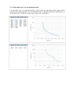
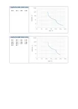
Страница 91: ...ion of overload operation It is recommended to use it within the continuous operation stage of torque speed curve For the torque speed curve please refer to appendix 9 Applicable model motor code 5022 5822 5003 5803 50C3 58C3 5004 5804 50C4 58C4 4004 50C5 58C5 5011 5811 50D1 58D1 4011 4012 50D7 5012 50D2 Applicable model motor code 5072 5872 9072 9872 ...

Страница 92: ...Applicable model motor code 5072 5872 9072 9872 Applicable model motor code 5033 9033 4031 4032 4042 5042 4044 5044 5078 5079 5077 5877 9077 9877 ...

Страница 93: ...rent requirements for servo responsiveness the following figure is the basic process of gain adjustment please adjust according to the current machine status and operation conditions Start adjusting Use adaptive 3kw auto tune function 3kw Are you satisfied with responsiveness YES Fast adjusting Are you satisfied with responsiveness NO YES NO Auto tuning external or internal instruction Are you sat...

Страница 94: ... 6 1 3 Model loop control In the auto tuning mode besides the gain of speed loop and position loop there is also the gain of model loop which has a great influence on the servo responsiveness When the model loop is not open the servo responsiveness is determined by the gain of the position loop and when the model loop is open the servo responsiveness is determined by the gain of the model loop The...

Страница 95: ...on to the adjustment of no overshoot in the positioning purpose In addition to gain adjustment the model loop gain and notch filter are also adjusted automatically Model loop function Parameter Meaning Default setting Modification Effective P2 47 n 0 Model loop turn off n 0 At anytime At once n 1 Model loop turn on Taking DS5 series servo auto tuning mode and using 750W servo 5 times load inertia ...

Страница 96: ...will be closed automatically and the gain of the disturbance observer will not change If the fast positioning or fast positioning control overshoot is selected the disturbance observer will be opened automatically and the gain of the disturbance observer will be modified to 85 The relevant parameters of this function no need to be set manually by users Parameter Meaning Default setting Modificatio...

Страница 97: ...ognition upper limit is 200 times parameter upper limit is 20000 If the estimated inertia ratio is exactly 20000 it means that the inertia ratio has reached the upper limit and can not be used please replace the motor with larger rotor inertia Other notes At present the inertia switching function is not supported and the second inertia ratio is invalid The inertia ratio upper limit changes to 500 ...

Страница 98: ...eral forward and reverse operations If the inertia identification error occurs the error code will be displayed Press STA ESC key to exit the panel inertia identification operation Alarm for inertia identification of panel Error code Meaning Reasons and solutions Reasons Err 1 Motor Torque Saturation Initial inertia is too small in adaptive mode switch to large inertia mode P2 03 3 1 or the initia...

Страница 99: ...e Enable have been opened P5 20 can be set to 0 first When the driver alarms it will appear Press ESC key to exit the auto tuning interface to see if there is an alarm Will occur when enable is turned on or driver has alarm Err 7 The driver alarms in the process of inertia identification Driver has alarm press ESC key to exit the auto tuning interface check the alarm code first solve the alarm and...

Страница 100: ...3 Set the auto tuning interface 4 Click ok to start inertia identification ...

Страница 101: ... of gain parameters belongs to auto tuning mode 6 3 2 Fast adjustment steps 1 estimate the load inertia through servo driver panel or XinJeServo software refer to chapter 6 2 2 shut down adaptive mode set P2 01 0 to 0 3 set the rigidity level P0 04 Note P2 01 0 is the first bit of P2 01 P2 01 n 0 0 1 0 P2 01 0 6 3 3 Rigidity level corresponding gain parameters Rigidity level P0 04 Rigidity level P...

Страница 102: ...d loop gain P1 01 speed loop integral P1 02 Position loop gain P2 35 Torque instruction filter P2 49 Model loop gain 33 1050 606 950 10 3300 34 1100 578 1000 10 3400 35 1150 553 1050 10 3500 36 1200 530 1100 10 3600 37 1250 509 1100 10 3700 38 1300 489 1100 10 3800 39 1350 471 1200 10 3900 40 1400 454 1200 10 4000 41 1450 439 1250 10 4100 42 1500 424 1300 10 4200 43 1550 410 1350 10 4300 44 1600 3...

Страница 103: ... to equipment with very small inertia strong mechanical stiffness and high response Driver power Default parameters Rigidity level 200w 750w P1 00 300 P1 01 2200 P1 02 300 P2 35 100 P2 49 400 15 100w P1 00 400 P1 01 1650 P1 02 400 P2 35 100 P2 49 500 20 6 3 4 Notes The gain parameters corresponding to the rigidity level can be independently fine tuned in the fast adjustment mode In order to ensure...

Страница 104: ...to failure Excessive load moment of inertia The moment of inertia varies greatly during operation Low mechanical rigidity vibration during operation and failure of detection positioning The running distance is less than 0 5 circles Preparations before auto tuning Use position mode Driver in BB state Driver without alarm The matching of the number of pulses per rotation and the width of positioning...

Страница 105: ...ing fails it is necessary to initialize the driver before auto tuning again Panel alarm in auto tuning process Error code Meaning Reasons Err 1 Failure to search for optimal gain Too large inertia ratio too weak rigidity of mechanism Err 2 Overtrip alarm in auto tuning process Please make sure that there is no overrun and alarm before auto tuning Err 6 Driver is not in bb state at the time of oper...

Страница 106: ...3 set the auto tuning interface ...

Страница 107: ...ll screw mechanism If there is no corresponding mechanism please choose this type Rigid connection It is suitable for the adjustment of rigid body system and other mechanisms with higher rigidity Auto tuning mode Description Soft Make a soft gain adjustment Besides gain adjustment notch filter is automatically adjusted Fast positioning Make special adjustment for positioning purpose Besides gain a...

Страница 108: ...hoot In the use of positioning we should pay attention to adjusting without overshoot Besides gain adjustment the model loop gain and notch filter are automatically adjusted 6 Start auto tuning 7 Wait for the end of the auto tuning ...

Страница 109: ...tion auto tuning Note in the auto tuning process press STA ESC will exit the auto tuning and use the gain parameters at the exit moment Panel error alarm in auto tuning process Error code Meaning Reasons Err 1 Failure to search for optimal gain Too large inertia ratio too weak rigidity of mechanism Err 2 Overrun alarm occurs during auto tuning External instruction auto tuning Vibration suppression...

Страница 110: ...2 Select jog or manual setting to configure the trip of inertia identification 3 Set the auto tuning interface 4 Click ok to start the inertia identification ...

Страница 111: ... control overshoot In the use of positioning we should pay attention to adjusting without overshoot Besides gain adjustment the model loop gain and notch filter are automatically adjusted Load type Description Synchronous belt Adjustment of lower rigidity mechanism such as synchronous belt Screw It is suitable for adjusting higher rigidity mechanism such as ball screw mechanism If there is no corr...

Страница 112: ...with higher rigidity 6 Start auto tune 7 Open the servo enable then click ok ...

Страница 113: ... ratio Gain performance parameters Yes P1 00 First speed loop gain P1 01 Integral time constant of the first speed loop P1 02 First position loop gain P2 00 0 Disturbance observer switch P2 01 0 Adaptive mode switch P2 35 Torque command filter time constant 1 P2 41 Disturbance observer gain P2 47 0 model loop switch P2 49 model loop gain P2 55 model speed feedforward gain P2 60 0 Active vibration ...

Страница 114: ...setting parameters No P2 86 auto tuning jog mode P2 87 auto tuning min limit position P2 88 auto tuning max limit position P2 89 auto tuning max speed P2 90 auto tuning acceleration deceleration time Note P2 60 P2 67 are automatically modified in auto tuning process Users are not allowed to modify them manually Manual modification may lead to the risk of system runaway 6 5 Manual adjustment 6 5 1 ...

Страница 115: ...e manual adjustment in the following occasions When the expected effect can not be achieved by fast adjusting the gain When the expected effect is not achieved by automatically adjusting the gain 6 5 2 Adjustment steps In position mode if the soft mode P2 02 0 1 is selected by auto tuning the function of model loop will be turned off in speed mode the gain of position loop will be invalid Increasi...

Страница 116: ...nstant is too large it will overshoot or prolong the positioning time which will make the response worse The relationship between the gain of the speed loop and the integral time constant of the speed loop is approximately as follows P1 00 P1 01 636620 Parameter Name Default setting Unit Range Modification Effective P1 01 integral time constant of speed loop 3300 0 01ms 15 51200 Anytime At once Po...

Страница 117: ... setting Unit Range Modify Effective P2 49 Model loop gain 500 0 1Hz 10 20000 Anytime At once 6 6 Adaptive 6 6 1 Overview Adaptive function means that no matter what kind of machine and load fluctuation it can obtain stable response through automatic adjustment It starts to automatically adjust when servo is ON 6 6 2 Notes When the servo unit is installed on the machine it may produce instantaneou...

Страница 118: ...io 50 Servo bb At once P6 08 Adaptive large inertia mode speed observer gain 40 Servo bb At once P6 12 Adaptive large inertia mode max inertia ratio 50 Servo bb At once Note 1 DS5 series servo 750W and below driver default value is 400 other power section default value is 200 Note 2 DS5 series servo 400W and below driver default value is 70 other power section default value is 50 6 6 5 Recommended...

Страница 119: ...ncrease P2 11 Adaptive position loop gain coefficient 100 50 200 Adjust according to the need increasing will make the response fast reducing will make the response slow P2 16 Adaptive motor rotor inertia coefficient 100 100 200 Increasing will improve the servo rigidity and enhance anti disturbance ability can solve operation jitter P2 19 Adaptive bandwidth 50 70 40 80 Increasing will improve the...

Страница 120: ... Position mode 6 7 4 Vibration Suppression PC Software Auto tuning mode Panel vibration suppression 6 7 3 Vibration Suppression Panel XinJeServo Mechanical Characteristic Analysis 6 7 4 Vibration Suppression PC Software Auto tuning ad aptive mode Panel vibration suppression 6 7 7 vibration suppression easyFFT Note The firmware version of the drive is viewed through U2 07 6 7 3 Vibration suppressio...

Страница 121: ...tion auto tuning Vibration Suppression Mode Servo turns off the Enabler in auto tuning process Please make sure that there is no overrun and alarm before auto tuning Make sure that the enabler is not turned off when auto tuning Err 3 Non position control mode please auto tune in position mode Err 4 Not turn off the adaptive function please set P2 01 0 to 0 then auto tune Err 7 Driver alarm in auto...

Страница 122: ...ation suppression manual setting If the resonance frequency of the mechanical system is known the vibration can be eliminated by setting the vibration frequency manually Please configure the third to fifth notches The related parameters are detailed in 6 7 7 notch filter 6 7 6 Vibration suppression quick FFT This function can analyze the mechanical characteristics through the parameter F0 12 on th...

Страница 123: ...R enter read to enable status it will show F 4 Press ENTER enable it will show run 5 Press INC DEC to run forward or reverse and find the resonance frequency E_FFt will shining on the panel when operation If the resonance frequency is found it will show Fxxxx xxxx is the resonance frequency If failed it will show F 6 Whatever it shown Fxxxx or F press INC DEC can find the resonance frequency again...

Страница 124: ...d the third fourth and fifth are set manually The torque instruction filter and notch filter are in series in the system As shown in the figure below the switch of the notch filter is controlled by P2 69 and P2 70 Torque command filter P2 35 First notch filter P2 71 P2 72 P2 73 Second notch filter P2 74 P2 75 P2 76 Third notch filter P2 77 P2 78 P2 79 Fourth notch filter P2 80 P2 81 P2 82 Fifth no...

Страница 125: ...frequency 5000 Hz 50 5000 Anytime At once P2 81 Fourth notch attenuation 70 0 1dB 50 1000 Anytime At once P2 82 Fourth notch bandwidth 0 Hz 0 1000 Anytime At once P2 83 Fifth notch frequency 5000 Hz 50 5000 Anytime At once P2 84 Fifth notch attenuation 70 0 1dB 50 1000 Anytime At once P2 85 Fifth notch bandwidth 0 Hz 0 1000 Anytime At once Note 1 In the adaptive mode if the vibration is detected t...

Страница 126: ...shing Countermeasure 1 Reducing gain parameters 2 Optimize the instructions of the upper device and reduce the acceleration of the instructions 6 8 2 Vibration The following causes cause machine vibration 1 Vibration due to inappropriate servo gain Countermeasure Reduce gain 2 Mechanical resonance point Countermeasure Setting notch parameters manually or through mechanical characteristic analysis ...

Страница 127: ...No Servo run 2 E 022 Parameter conflict No Servo run 3 E 023 Sampling channel setting error Yes Servo run 4 E 024 parameter lost No Servo run 5 E 025 Erase FLASH error No Servo run 6 E 026 InitializationFLASHerror No Servo run 8 E 028 EEPROM write in error No Servo run 03 0 E 030 Bus voltage overvoltage No Servo off 04 0 E 040 Bus voltage under voltage Low grid voltage No Servo run Bus voltage und...

Страница 128: ...grating ruler counter direction reverse Yes Servo off 8 E 238 Full closed loop external grating scale speed overrun Yes Servo off 24 0 E 240 Timing error in fetching encoder position data No Servo off 1 E 241 Encoder reponse data is error code No Servo off 26 0 E 260 Over range alarm No Servo run 1 E 261 Overrun signal connection error No Servo run 2 E 262 Control stop timeout No Servo off 4 E 264...

Страница 129: ... voltage whether the input phase is missing or the supply voltage is too low Contact agent or manufacturer 7 E 017 Processor Running Timeout Program damage Please contact the agent or the manufacturer 9 E 019 System password error Program damage Please contact the agent or the manufacturer 02 0 E 020 Parameter loading error Failure of parameter self checking Re energizing can restore default param...

Страница 130: ...ee chapter 1 4 1 for the selection of the external resistor Acceleration and deceleration time is too short Extending Acceleration and Deceleration Time Hardware Fault of Driver Internal Sampling Circuit The AC gear of the multimeter measures the input value of the servo LN R S T which is 220V 10 of the normal value If the power supply voltage is more than 220V 10 380V 10 check the power supply vo...

Страница 131: ...sive ambient temperature 1 Enhance ventilation measures to reduce ambient temperature 2 Check whether the fan rotates when the servo is enabled when the module temperature U 06 45 the fan opens Fan damage Replace the fan 1 E 061 Motor overheat Alarm when motor temperature is higher than 95 Check whether the motor fan is abnormal Contact the manufacturer for technical support 3 E 063 Thermocouple d...

Страница 132: ...ircuit Discovered in Self Inspection Not match the motor code Check if the driver P0 33 is identical with the motor code of the motor label the number after MOTOR CODE if not please change to the same one then power on again UVW wiring error Inspection of motor UVW wiring need to be in phase sequence brown U black V blue W Driver UVW Output Short Circuit or Motor Failure 1 Measure whether the UVW ...

Страница 133: ...l be considered improper selection of the motor Increase the capacity of drivers and motors Extend the acceleration and deceleration time and reduce the load Monitor the U 00 whether it is running over speed Mechanisms are impacted suddenly weighted and distorted Eliminate mechanical distortion Reduce load Motor action when motor brake is not opened Measure the voltage of the brake terminal and de...

Страница 134: ...f it is not servo control attention must be paid to the timing of brake opening and motor action 3 Monitor the actual output torque range of U0 02 and check whether the setting of P3 28 29 torque limit is reasonable After version 3760 the output torque limit setting parameters of anti locked rotor alarm are P3 38 and P3 39 20 0 E 200 Regenerative resistance overload High Voltage Fluctuation in Pow...

Страница 135: ...encoder error retry number register P0 56 Encoder interfered isolate interference source 2 E 222 Absolute value servo encoder battery low voltage alarm can shield this alarm Battery Voltage in Battery Box of Encoder cable is less than 2 75V Please replace the battery while keeping the power supply ON of the servo driver in order to avoid the error of encoder position information Battery specificat...

Страница 136: ...lution exceeds the setting value of P9 02 Mechanism error The motor outputs the shaft position directly and reaches the moving platform through the mechanism The feedback of the grating ruler is directly from the moving platform and there will be errors in it after passing through the synchronous belt or lead screw Grating ruler installation is not parallel Set P9 05 to P9 08 reasonably 7 E 237 Fu...

Страница 137: ...n is too small which leads to the oscillation of positioning 1 Check the source of external force to see if there are any problems in mechanical installation 2 Increase the servo gain to improve the anti disturbance ability 3 Acquisition speed curve analysis When the first three peaks are convergenced after pulse instruction completed 0 8 first peak second peak and 0 8 second peak third peak the d...

Страница 138: ...rent motor parameter performance Read the alarm shielding position of motor parameters through p0 53 and set the motor code of P0 33 correctly At this time the motor parameters are in the driver which can work normally but may affect some performance 4 E 314 Motor code does not match software version Encoder hardware version is higher than driver firmware version Contact the manufacturer s technic...

Страница 139: ...X 0 PX XX 1 PX XX 2 PX XX 3 P0 XX Parameter Function Unit Default value Range Effective Suitable mode Reference chapter P0 01 Control mode 1 1 Internal Torque Mode 2 External Analog Torque Mode 3 Internal speed Model 4 External Analog speed Mode 5 Internal Location Mode 6 External Pulse Position Mode 7 External Pulse speed Mode 8 XNET Bus Torque Mode 9 XNET Bus Speed Mode 10 XNET Bus Location Mode...

Страница 140: ...command pulses required for motor rotation 1 pul 10000 0 99999999 5 6 5 3 1 1 P0 13 Electronic Gear Numerator 1 0 65535 5 6 5 3 1 1 P0 14 Denominator of Electronic Gear 1 0 65535 5 6 5 3 1 1 P0 15 Pulse frequency corresponding to rated speed 100Hz 1000 1 10000 7 5 4 3 2 P0 16 Speed command pulse filter time 0 01ms 100 0 10000 7 5 4 3 3 P0 18 Encoder feedback pulse number per turn low bit 0 0 0 999...

Страница 141: ... 10 5 2 4 P0 30 stop timeout time 1ms 20000 0 65535 1 2 3 4 5 6 7 8 9 10 5 2 3 P0 31 Deceleration stop time 1ms 25 0 5000 1 2 3 4 5 6 7 8 9 10 5 2 3 P0 33 Set the motor code 0 0 ffff 1 2 3 4 5 6 7 8 9 10 4 7 Parameter Function Unit Default value Range Effective Suitable mode Reference chapter P0 53 Read motor parameter alarm shield bit 0 not shield alarm shield alarm 0 0 1 1 2 3 4 5 6 7 8 9 10 P0 ...

Страница 142: ...tor take effect when P0 11 P0 14 is 0 P0 94 1 P0 95 10000 1 1 9999 5 6 5 3 1 1 1 65535 P1 XX Parameter Function Unit Default value Range Effective Suitable mode Reference chapter P1 00 First speed loop gain 0 1Hz 20P1 400 Others 200 10 20000 1 2 3 4 5 6 7 8 9 10 6 5 3 P1 01 Integral Time Constant of the First Speed Loop 0 01ms 20P1 1650 Others 3300 15 51200 1 2 3 4 5 6 7 8 9 10 6 5 3 P1 02 First p...

Страница 143: ...ronous belt 2 screw rod 3 Rigid Connection 2 1 3 1 2 3 4 5 6 7 8 9 10 6 1 3 P2 03 3 Adaptive load type 0 Small Inertia Mode 1 Large Inertia Mode 0 0 1 1 2 3 4 5 6 7 8 9 10 6 6 4 P2 05 Adaptive mode speed loop gain standard 0 1Hz 20P1 20P2 20P4 20P7 400 21P5 200 1 65535 1 2 3 4 5 6 7 8 9 10 6 6 4 P2 07 Adaptive mode inertia ratio standard 0 0 10000 1 2 3 4 5 6 7 8 9 10 6 6 4 P2 08 Gain of adaptive ...

Страница 144: ...3 4 5 6 7 10 6 4 6 P2 60 1 Active Suppression Auto tuning Switch 0 Active Vibration Suppression is not Configured in auto tuning 1 configure the Active Vibration Suppression when auto tuning 1 0 1 3 4 5 6 7 10 6 4 6 P2 61 Active Vibration Suppression frequency 0 1Hz 1000 10 20000 1 2 3 4 5 6 7 8 9 10 6 5 P2 62 Active Vibration Suppression gain 100 1 1000 1 2 3 4 5 6 7 8 9 10 6 4 6 P2 63 Active Vib...

Страница 145: ... attenuation 0 1dB 70 50 1000 1 2 3 4 5 6 7 8 9 10 6 7 7 P2 79 Third notch band width Hz 0 0 1000 1 2 3 4 5 6 7 8 9 10 6 7 7 P2 80 Fourth notch frequency Hz 5000 50 5000 1 2 3 4 5 6 7 8 9 10 6 7 7 P2 81 Fourth notch attenuation 0 1dB 70 50 1000 1 2 3 4 5 6 7 8 9 10 6 7 7 P2 82 Fourth notch band width Hz 0 0 1000 1 2 3 4 5 6 7 8 9 10 6 7 7 P2 83 Fifth notch frequency Hz 5000 50 5000 1 2 3 4 5 6 7 8...

Страница 146: ...3 3 4 7 5 4 1 2 P3 13 Zero speed clamping speed rpm 10 0 300 3 4 7 5 4 1 2 P3 14 Forward Maximum Speed Instruction Limit rpm 4000 0 10000 1 2 3 4 5 6 7 10 5 8 3 P3 15 Reverse Maximum Speed Instruction Limit rpm 4000 0 10000 1 2 3 4 5 6 7 10 5 8 3 P3 16 Internal Forward Speed Limitation in Torque Control rpm 2000 5 10000 1 2 5 5 1 2 P3 17 Internal Reverse Speed Limitation in Torque Control rpm 2000...

Страница 147: ... 300 0 1000 1 2 3 4 5 6 7 8 9 10 5 8 2 P3 31 external reverse torque limit 300 0 1000 1 2 3 4 5 6 7 8 9 10 5 8 2 P3 32 Brake torque 1 300 0 1000 1 2 3 4 5 6 7 8 9 10 5 2 4 P3 33 Preset torque 0 1000 1000 1 5 5 1 1 P3 45 Torque mode switching delay ms 40 0 9999 1 2 P4 XX Parameter Function Unit Default value Range Effective Suitable mode Reference chapter P4 00 0 Z phase signal numbers The Z phase ...

Страница 148: ...nal position mode start segment No 1 0 35 5 5 3 3 3 P4 10 P4 11 First segment pulse 1pul 0 32768999 9 327679 999 5 5 4 3 P4 12 First segment speed 0 1rpm 0 0 65535 5 5 4 3 P4 13 First segment acceleration time 1ms 0 0 65535 5 5 4 3 P4 14 First segment deceleration time 1ms 0 0 65535 5 5 4 3 P4 16 Adjusting time 1ms 0 0 65535 5 5 4 3 P4 10 n 1 7 P4 16 n 1 7 segment 1 to 35 pulse parameters n is seg...

Страница 149: ... 65535 1 2 3 4 5 6 7 8 9 10 5 8 5 7 P5 14 Custom Output 2 Trigger Condition 0 0 ffff 1 2 3 4 5 6 7 8 9 10 5 8 5 7 P5 15 Set a value that compares with the trigger condition of custom output 2 Relating to trigger condition 0 9999 99 99 1 2 3 4 5 6 7 8 9 10 5 8 5 7 P5 16 Select custom output 2 mode 0 0 3 1 2 3 4 5 6 7 8 9 10 5 8 5 7 P5 17 Setting custom output 2 hysteresis Relating to trigger condit...

Страница 150: ... 9 10 5 8 2 P5 25 2 SI terminal filtering time ms 0 0 f 1 2 3 4 5 6 7 8 9 10 5 8 4 1 P5 26 0 1 N CL External Torque Limitation at Reverse Rotation Side 00 0 ff 1 2 3 4 5 6 7 8 9 10 5 8 2 P5 26 2 SI terminal filtering time ms 0 0 f 1 2 3 4 5 6 7 8 9 10 5 8 4 1 P5 27 0 1 SPD D Internal Speed Direction Selection 00 0 ff 1 2 3 4 7 5 4 2 P5 27 2 SI terminal filtering time ms 0 0 f 1 2 3 4 7 5 8 4 1 P5 ...

Страница 151: ...n 0001 0 ffff 5 6 10 5 3 1 2 P5 39 V CMP same speed detection 0000 0 ffff 3 4 7 5 8 5 3 P5 40 TGON rotation detection 0000 0 ffff 1 2 3 4 5 6 7 8 9 10 5 8 5 2 P5 41 S RDY ready 0000 0 ffff 1 2 3 4 5 6 7 8 9 10 5 8 5 1 P5 42 CLT torque limit 0000 0 ffff 1 2 3 4 5 6 7 8 9 10 5 8 2 P5 43 VLT speed limit detection 0000 0 ffff 1 2 5 5 1 3 P5 44 BK brake locking 0000 0 ffff 1 2 3 4 5 6 7 8 9 10 5 2 5 P5...

Страница 152: ... 0 0 f 5 P5 70 SRDY Output Conditions Selection 0 This terminal is turned on after initialization of the driver is completed 1 This terminal will not turn on until enabled 0 0 1 1 2 3 4 5 6 7 8 9 10 5 8 5 1 P5 71 Function Selection of Directional Terminal of Pulse Speed Mode 0 0 1 7 5 4 3 4 P6 XX Parameter Function Unit Default value Range Effective Suitable mode Reference chapter P6 05 Adaptive M...

Страница 153: ...000 U0 18 Torque current 0 01A U0 19 Analog input V REF value 0 01V U0 20 Analog input T REF value 0 01V U0 21 Input signal status 1 U0 22 Input signal status 2 U0 23 output signal status 1 U0 24 ouput signal status 2 U0 25 Input pulse frequency 0000 9999 1 1Hz U0 26 0000 9999 10000 U0 37 VREF AD Raw value U0 38 TREF AD Raw value U0 41 Instantaneous output power 1W U0 42 Average output power 1W U0...

Страница 154: ...0 65536 216 U0 96 0000 65536 232 U0 97 0000 65536 U1 XX Code Contents Unit U1 00 present alarm code U1 01 present warning code U1 02 U phase current when alarming 0 01A U1 03 V phase current when alarming 0 01A U1 04 bus voltage when alarming V U1 05 IGBT temperature when alarming U1 06 torque current when alarming 0 01A U1 07 excitation current when alarming A U1 08 position offset when alarming ...

Страница 155: ... from this time power on second U2 15 Average output power from the first time enabled average power in the process of enabling 1W U2 16 Average thermal power from the first time enabled average power in the process of enabling 1W U2 17 Average bus capacitor filter power from the first time power on average power in the process of power on 1W U2 20 Device serial no low 16 bit U2 21 Device serial n...

Страница 156: ... address is added 1 in turn from 0x0100 for example Modbus address of P1 10 is 0x010A P2 15 P2 xx 0x020F 0x0263 Modbus address is added 1 in turn from 0x020F for example Modbus address of P2 16 is 0x0210 P3 00 P3 xx 0x0300 0x0363 Modbus address is added 1 in turn from 0x0300 for example Modbus address of P3 13 is 0x030D P4 00 P4 xx 0x0400 0x0463 Modbus address is added 1 in turn from 0x0400 for ex...

Страница 157: ...07 0x0007 7 P0 24 0x0018 24 P0 08 0x0008 8 P0 25 0x0019 25 P0 09 0x0009 9 P0 26 0x001A 26 P0 10 0x000A 10 P0 27 0x001B 27 P0 11 0x000B 11 P0 28 0x001C 28 P0 12 0x000C 12 P0 29 0x001D 29 P0 13 0x000D 13 P0 30 0x001E 30 P0 14 0x000E 14 P0 31 0x001F 31 P0 15 0x000F 15 P0 32 0x0020 32 P0 16 0x0010 16 P0 33 0x0021 33 Parameter Modbus address Parameter Modbus address Hex Decimal Hex Decimal P1 00 0x0100...

Страница 158: ...1 801 P3 15 0x030F 783 P3 34 0x0322 802 P3 16 0x0310 784 P3 35 0x0323 803 P3 17 0x0311 785 P3 36 0x0324 804 P3 18 0x0312 786 Parameter Modbus address Parameter Modbus address Hex Decimal Hex Decimal P4 00 0x0400 1024 P4 15 0x040F 1039 P4 01 0x0401 1025 P4 16 0x0410 1040 Parameter Modbus address Parameter Modbus address Hex Decimal Hex Decimal P5 00 0x0500 1280 P5 27 0x051B 1307 P5 01 0x0501 1281 P...

Страница 159: ...792 P7 10 0x070A 1802 P7 01 0x0701 1793 Monitoring status address of group U Parameter Modbus address Parameter Modbus address Hex Decimal Hex Decimal U0 00 0x1000 4096 U0 28 0x101C 4124 U0 01 0x1001 4097 U0 29 0x101D 4125 U0 02 0x1002 4098 U0 30 0x101E 4126 U0 03 0x1003 4099 U0 31 0x101F 4127 U0 04 0x1004 4100 U0 32 0x1020 4128 U0 05 0x1005 4101 U0 33 0x1021 4129 U0 06 0x1006 4102 U0 34 0x1022 41...

Страница 160: ...15 U1 08 0x1108 4360 U2 08 0x1208 4616 U1 09 0x1109 4361 U2 09 0x1209 4617 U1 10 0x110A 4362 U2 10 0x120A 4618 U1 11 0x110B 4363 U2 11 0x120B 4619 U1 12 0x110C 4364 U2 12 0x120C 4620 U1 13 0x110D 4365 U2 13 0x120D 4621 U1 14 0x110E 4366 U2 14 0x120E 4622 U1 15 0x110F 4367 U2 15 0x120F 4623 U1 16 0x1110 4368 U2 16 0x1210 4624 U1 17 0x1111 4369 U2 17 0x1211 4625 U1 18 0x1112 4370 U2 20 0x1214 4628 U...

Страница 161: ...SI1 SI2 SI3 SI4 24V SO1 SO2 COM 1 P5 44 defines the terminal of the brake output signal As shown in the figure above the SO1 controls brake that is P5 44 0001 2 Extend the delay time of servo OFF P5 07 default 500ms and the waiting time of braking instruction P5 09 is set to 0 which can be responded Q7 The initial direction is not what I want How can I change it through a servo driver Change the i...

Страница 162: ...en the built in resistor specifications are insufficient the external resistor should be replaced The specifications of the external regenerative resistor please refer to chapter 1 4 1 1 P D C interface model Remove the short joint between P D and connect the external regenerative resistance to P C 2 P PB interface model connect external regenerative resistance to P PB 3 Version number parameter U...

Страница 163: ...r supply immediately and re check the wiring situation Long press ENTER Short press ENTER Press DEC Press INC C jog run Enter F1 00 Short press ENTER to enable the motor In the enabled status press INC for run forward press DEC to run reverse Press STATUS ESC to exit Four status when jog running status Panel display status Panel display Idle Forward run enabled Reverse run 2 Debug the motor with t...

Страница 164: ...s 1 Make sure the work mode 6 2 It needs to judge whether 2 and 3 touch 1 when finding the symmetrical point first time The sign is servo output torque will increase It needs to use torque limit P3 28 P3 29 and torque limit output signal CLT 3 As the dimension of workpiece 1 is larger than standard offset pulse will remain in servo when the symmetrical point is found CLR signal can clear the pulse...

Страница 165: ...se command state P0 10 2 Electronic gear ratio P0 11 0 P0 12 0 P0 13 16384 P0 14 625 Forward torque limit P3 28 150 Reverse torque limit P3 29 150 Positioning finished width P5 00 7 S ON P5 20 0010 CLR P5 34 0001 COIN P5 38 0001 CLT P5 42 0002 ...

Страница 166: ...minal to control the setting parameters of holding brake P5 47 alarm output ALM output alarm function setting through the SO terminal SO2 terminal default output is dynamic closing signal P7 00 RS485 Station No P7 01 communication configuration P7 02 RS485 communication protocol Communication setting related parameters Appendix 8 2 External pulse position mode general parameters External pulse pos...

Страница 167: ...ue control general parameters Internal torque control Parameter Overview P0 01 control mode selection Set to 1 internal torque mode P3 33 Internal torque command given The given value is the percentage of rated torque P3 16 internal forward speed limit for torque control P3 17 internal reverse speed limit for torque control P3 14 forward maximum speed limit max speed P3 15 reverse maximum speed li...

Страница 168: ...speed mode P0 10 pulse command format Set the pulse format 0 CW CCW 1 AB 2 P D P0 15 Command pulse frequency at rated speed Determine the linear relationship between the command pulse frequency and the speed P0 16 Speed command pulse filtering time When the command pulse frequency is relatively low setting this parameter properly can reduce the speed fluctuation ...

Страница 169: ...Appendix 9 Torque speed characteristic curve ...

Страница 170: ......

Страница 171: ...We chat ID WUXI XINJE ELECTRIC CO LTD 4th Floor Building 7 Originality Industry park Liyuan Development Zone Wuxi City Jiangsu Province 214072 Tel 510 85134136 Fax 510 85111290 ...

Отзывы: