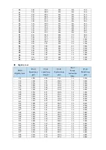
60
2400
265
2400
10
6000
61
2450
259
2450
10
6000
62
2500
254
2500
10
6000
63
2600
244
2600
10
6000
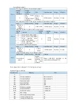
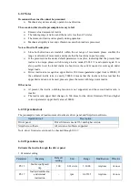
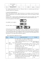
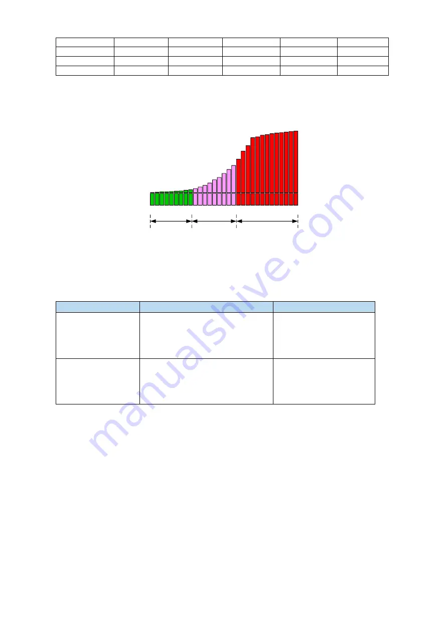
The rigidity level should be set according to the actual load. The larger the P-04 value, the greater the
servo gain. If there is vibration in the process of increasing the rigidity level, it is not suitable to
continue to increase. If vibration suppression is used to eliminate vibration, it can try to continue to
increase. The following is the recommended rigidity level of the load, for reference only.
1
20
40
60
Large Load of
Flexible Structure
High Rigid
Load
Light-load Ultra-
high Response Load
Flexible structure large load: refers to the type of synchronous belt structure, large load inertia
equipment.
High rigid load: refers to the mechanism of screw rod or direct connection, and equipment with strong
mechanical rigidity.
Ultra-high response load under light load: refers to equipment with very small inertia, strong
mechanical stiffness and high response.
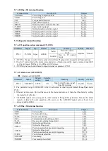
Driver power
Default parameters
Rigidity level
200w
~
750w
P1-00=300
P1-01=2200
P1-02=300
P2-35=100
P2-49=400
15
100w
P1-00=400
P1-01=1650
P1-02=400
P2-35=100
P2-49=500
20
6.3.4 Notes
The gain parameters corresponding to the rigidity level can be independently fine-tuned in
the fast adjustment mode.
In order to ensure stability, the gain of model loops is small at low rigidity level, which can
be added separately when there is high response requirement.
When vibration occurs in fast adjustment, the torque instruction filter P2-35 can be modified.
If it is ineffective, the mechanical characteristic analysis can be used and the relevant notch
parameters can be set (refer to chapter 6.7 vibration suppression).
Fast adjustment mode defaults to set a rigidity level. If the gain does not meet the mechanical
requirements, please gradually increase or decrease the settings.
At present, gain switching function is not supported, that is, the second gain parameters such
as P1-05, P1-06, P1-07 are invalid.
Содержание DS5L1 Series
Страница 1: ...DS5L1 series servo driver User manual WUXI XINJE ELECTRIC CO LTD Data No SC5 05 20200929 1 0 ...
Страница 2: ......
Страница 6: ......
Страница 33: ...Voltage DC 30V maximum Current SO1 DC 500mA maximum 400W and below servo can support SO others DC 50mA maximum ...
Страница 100: ...3 Set the auto tuning interface 4 Click ok to start inertia identification ...
Страница 106: ...3 set the auto tuning interface ...
Страница 112: ...with higher rigidity 6 Start auto tune 7 Open the servo enable then click ok ...
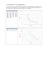
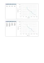
Страница 169: ...Appendix 9 Torque speed characteristic curve ...
Страница 170: ......

