


2
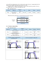
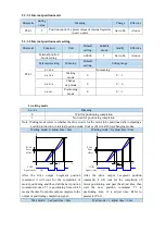
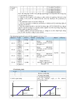
When
the
instruction
ends
and
the
motor
speed is under the
rotation detection
speed (P5-03) and
the
absolute
deviation is less
than P5-00,
the
COIN
signal
is
output.
|
U0-08
|
Pulse offset
P5-00
ON
/S-ON
Signal status
/COIN
Signal status
ON
ON
OFF
|
ΔU0-12
|
Pulse command
|
U0-00
|
Actual speed
P5-03
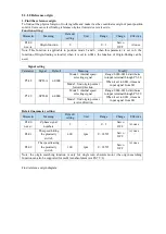
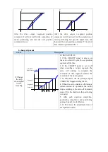
3
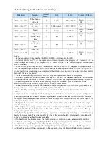
At the end of
instruction,
the
absolute deviation
value under P5-00,
it outputs COIN
signal. If COIN
maintains
P5-02
time, COIN-HOLD
signal is output.
|
U0-08
|
Pulse offset
P5-00
ON
/S-ON
Signal status
/COIN
Signal status
ON
ON
OFF
|
ΔU0-12
|
Pulse command
/COIN-HOLD
Signal status
ON
OFF
P5-02
P5-02
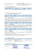
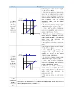
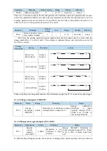
2. Description of positioning completion width
(1) The positioning completion width P5-00 changes proportionally due to the change of electronic
gear ratio, and the factory default is 11 command units.
The following table is an example:
Number of
command pulses
required for one
revolution of motor
positioning completion
width P5-00
The positioning completion width P5-00
changes proportionally with the number of command
pulses required for one revolution of the motor.
The output of the positioning completion signal
depends on the positioning completion width. The
smaller the width is, the later the positioning
completion signal output is, but the signal output
does not affect the actual operation state of the
motor.
10000 (default)
11 (default)
20000
22
5000
6
3000
4
2000
3
(2) The positioning completion width can also be set separately, and its change will not affect the
number of command pulses required for one revolution of the motor.
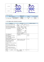
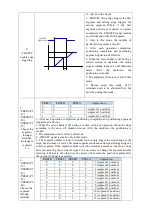
5.3.1.3 Positioning near signal (/NEAR)
The servo motor is located near the positioning completion signal, so that the equipment can prepare
the next action in advance.
Related parameters
Содержание DS5L1 Series
Страница 1: ...DS5L1 series servo driver User manual WUXI XINJE ELECTRIC CO LTD Data No SC5 05 20200929 1 0 ...
Страница 2: ......
Страница 6: ......
Страница 33: ...Voltage DC 30V maximum Current SO1 DC 500mA maximum 400W and below servo can support SO others DC 50mA maximum ...
Страница 100: ...3 Set the auto tuning interface 4 Click ok to start inertia identification ...
Страница 106: ...3 set the auto tuning interface ...
Страница 112: ...with higher rigidity 6 Start auto tune 7 Open the servo enable then click ok ...
Страница 169: ...Appendix 9 Torque speed characteristic curve ...
Страница 170: ......


