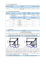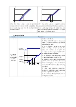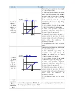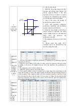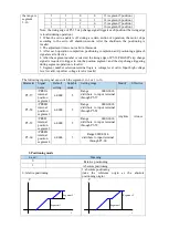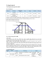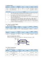
1. /INHIBIT terminal effectiveness description
Parameter setting
status
Signal/INHIBIT terminal input status
Signal/INHIBIT terminal
logic
P5-32=n.0000
No external terminal input
Invalid
P5-32=n.000□
SI□ terminal has no signal input
P5-32=n.001□
SI□ terminal has signal input
P5-32=n.0010
No external terminal input
Valid
P5-32=n.000□
SI□ terminal has signal input
P5-32=n.001□
SI□ terminal has no signal input
2. The influence of /INHIBIT terminal signal on the running state of motor
Control mode
Motor operation status
/INHIBIT terminal logic
valid
/INHIBIT terminal logic invalid
5- internal position
control
Pause current segment
/INHIBIT signal is from ON→OFF, continue
running from pause point.
6-
external
pulse
position control
Pause
pulse
command
reception
/INHIBIT signal is from ON→OFF, continue
running from the pulse command received
after OFF.
5.3.1.5 Offset clear
(
/CLR
)
Position offset=(position command – position feedback)(encoder unit)
The position deviation clearing function means that the driver can clear the position deviation
when the servo is off or the /CLR signal is received.
Related parameters
Parameter
Signal
name
Default
setting
Suitable
mode
Meaning
Modify
Effective
P5-34
/CLR
n.0000
All
Pulse deviation clear
Anytime
At once
Parameter range n.0000-001A, assigned to other input terminals by parameter P5-34.
If it is necessary to input signal from SI2, P5-34 can be set to n.0002/0012. Refer to section 3.2.2 for
hardware wiring details.
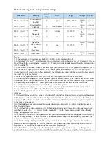
1. /CLR signal effectiveness
parameter setting status
Signal /CLR terminal input status
Signal /CLR terminal
logic
P5-34=n.0000
No external terminal input
Invalid
P5-34=n.000□
SI□ terminal has no signal input
P5-34=n.001□
SI□ terminal has signal input
P5-34=n.0010
No external terminal input
Valid
P5-34=n.000□
SI□ terminal has signal input
P5-34=n.001□
SI□ terminal has no signal input
2. /CLR signal explanation
Send the pulse to the servo, execute the /CLR input signal, the servo will lock the current pulse
counts, then update the current position of the encoder to the position feedback in the control, at the
same time, clear the intermediate quantity of the position loop, speed loop and current loop.
/CLR signal is triggered by edge.
3. Other description of pulse position deviation clearing signal
Setting F0-02 to 1 can also clear the pulse position deviation.
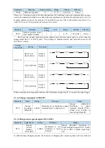
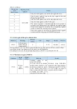
5.3.1.6 Position pulse deviation
Pulse deviation value refers to the difference between command pulse of command controller
Содержание DS5L1 Series
Страница 1: ...DS5L1 series servo driver User manual WUXI XINJE ELECTRIC CO LTD Data No SC5 05 20200929 1 0 ...
Страница 2: ......
Страница 6: ......
Страница 33: ...Voltage DC 30V maximum Current SO1 DC 500mA maximum 400W and below servo can support SO others DC 50mA maximum ...
Страница 100: ...3 Set the auto tuning interface 4 Click ok to start inertia identification ...
Страница 106: ...3 set the auto tuning interface ...
Страница 112: ...with higher rigidity 6 Start auto tune 7 Open the servo enable then click ok ...
Страница 169: ...Appendix 9 Torque speed characteristic curve ...
Страница 170: ......


