7PG2113/4/5/6 Commissioning & Maintenance
©2012 Siemens Protection Devices Limited
Chapter 6 Page 30 of 77
1
1
General Starter
51-n
51c-n Setting
51c-n Charact
51c-n Time Mult
51c-n Follower DTL
c
51c-n Reset
Cold Load
Enabled
L1 Dir En
L2 Dir En
L3 Dir En
Disabled
c
start
trip
c
start
trip
c
start
trip
51c-n Min. Operate Time
Reduced
Current
Enabled
Disabled
51c-n Delay (DTL)
CB Open
CB Closed
Pick-up Time
Drop-off Time
Reduced Current DTL
Reduced
Current Level
c
<
<
<
IL1
IL2
IL3
51c
See Delayed
Overcurrent
(51-n)
1
&
S
R
Q
&
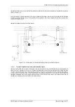
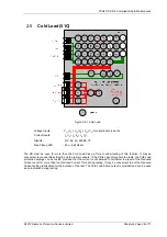
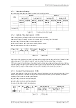
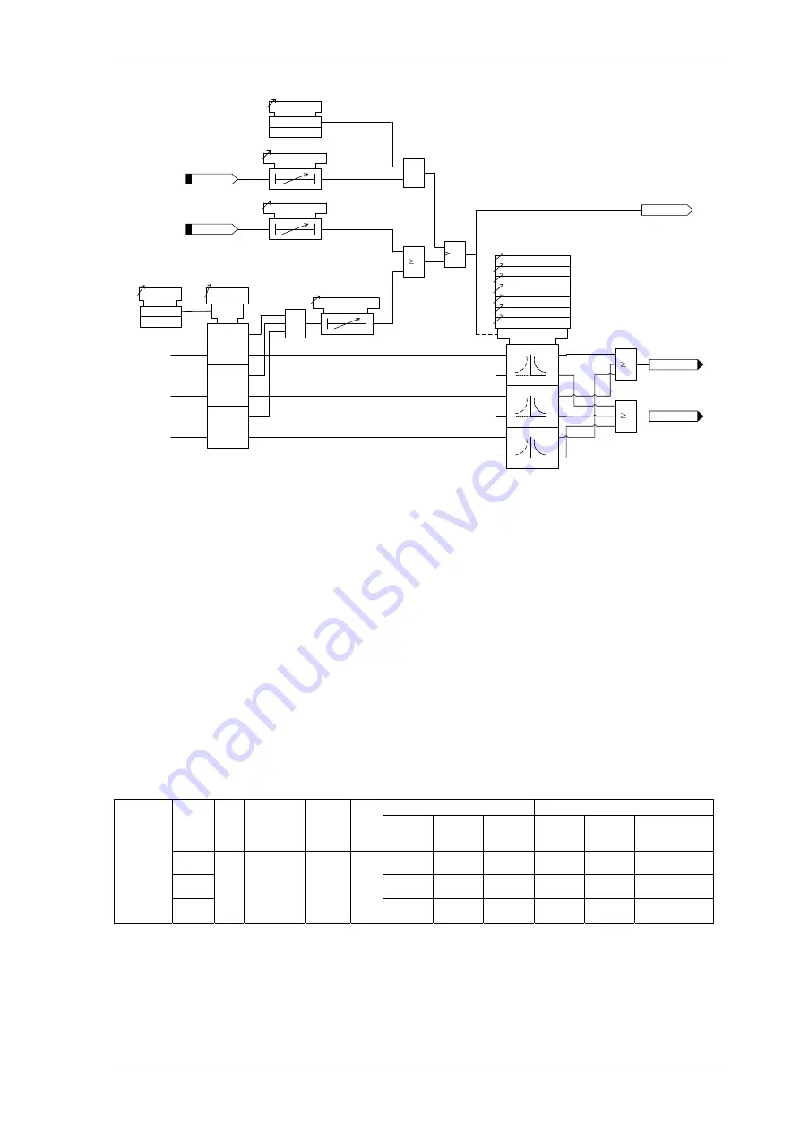
Figure 2.5-2 Cold Load Logic diagram
Ensure that the
Cold load active
is not raised. This can be reset by CB closed for more than the Cold Load
Drop-
off Time
or current less than the
Reduced Current Level
for greater than the
Reduced Current Time
. Check the
Cold Load Pick-up Delay by applying or simulating CB Open. Measure the time delay before
Cold Load Active
is
raised. Apply current above the
Reduced Current Level
if this functionality is Enabled before applying CB Closed.
Measure the time for
Cold Load Active
to reset.
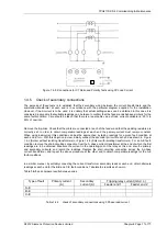
2.5.1 Inverse Time Overcurrent (51C)
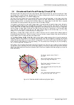
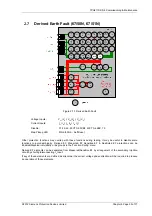
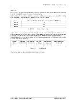
It will be advantageous to map the function being tested to temporarily drive the relevant Pickup output in the
Pickup Config
sub-menu in the
Output Config
menu as this will allow the Pick-up led to operate for the function.
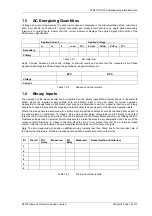
Gradually increase current until Pickup LED operates.
Apply 2x setting current and record operating time,
Apply 5x setting current and record operating time.
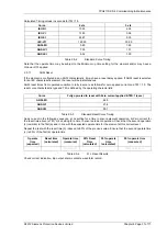
Compare to calculated values for operating times
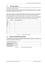
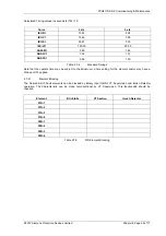
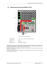
Table 2.5-1
51c Test Results
Operate Current
Operate Time
Ph. Dir
Char.
(NI EI VI
LTI, DTL)
Is
(A)
TM
P.U.
(Amps)
D.O.
(Amps)
Tol
2 x Is
(sec)
5 x Is
(sec)
Tol
I
L1
(I
A
)
I
L2
(I
B
)
P.U.
D.O.
&
TIMING
TESTS
I
L3
(I
C
)

