7PG2113/4/5/6 Performance Specification
©2010 Siemens Protection Devices Limited
Chapter 3 Page 10 of 42
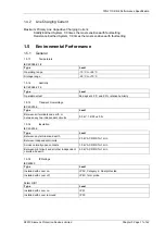
1.3
Functional performance
1.3.1 Instrumentation
Instrument Value
Reference
Typical accuracy
I Current
I
≥
0.1 xIn
±
1 % In or ± 5 mA
V Voltage
V
≥
0.8 xVn
±
1 % Vn
W,Var,
VA
Power, real and apparent
V = Vn, I
≥
0.1 xIn, pf
≥
0.8
±
3% Pn, where Pn = Vn x In
pf Power
factor
V = Vn, I
≥
0.1 xIn, pf
≥
0.8
±
0.05
1.3.2 USB 2.0 Data Communication Interface
Attribute Value
Physical layer
Electrical
Connectors USB-Type
B
1.3.3 RS485 Data Communication Interface
Attribute Value
Physical layer
Electrical
Connectors
4mm Ring Crimp
1.3.4 Real Time Clock
1.3.4.1
Internal Clock
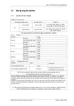
The specification below applies only while no external synchronisation signal (e.g. 60870-5-103) is being
received.
Attribute Value
Accuracy (-10 to +55
o
C)
±
3.5 p.p.m
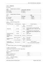
1.4
Current Differential Application Limits
1.4.1 Pilot Cable connection
Number of Pilot cores required 2
Pilot Requirements
R Mode
Rf Mode
Rf mode with 15kv Transf.
Tap 1
Tap 0.5
Tap 0.25
Max. Loop Resistance
1000
Ω
2000
Ω
1780
Ω
880
Ω
440
Ω
Max. Inter core Capacitance
2.5
μ
F 0.8
μ
F 1
μ
F 2
μ
F 4
μ
F
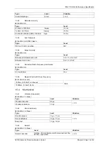
Pilot Current and Voltage
R Mode
Rf Mode
Rf mode with 15kv Transf.
Tap 1
Tap 0.5
Tap 0.25
Peak Voltage applied to pilots
under fault conditions
300v 450v 450v
330v
225v
Maximum current carried by pilots
under fault conditions
200mA 250mA 250mA
380mA
500mA

