7PG2113/4/5/6 Commissioning & Maintenance
©2012 Siemens Protection Devices Limited
Chapter 6 Page 7 of 77
1.2.3 Test
Equipment
Required test equipment is:
1. A 500V insulation-resistance test-set.
2. Secondary injection equipment with integral time interval meter
3. Primary
injection
equipment
4. A power source with nominal voltage within the working range of the relay's auxiliary supply rating.
5. A power source with nominal voltage within the working range of the relay’s d.c. binary input rating.
6. A multi purpose measuring instrument (multi-meter) suitable for measuring pilot resistance and low
levels of secondary AC current.
7. 200 watt 2000 ohm resister ( DC to AC inverter test ).
The secondary injection equipment should be appropriate to the protection functions to be tested.
During normal operation, power supply for the Solkor R/Rf circulating current system is derived directly from the
system current transformers. During testing, this power must be supplied by the current injection test equipment.
The operating burden of a connected pair of Solkor R/Rf relays is 1.5 – 3 VA at setting which corresponds to a
secondary voltage of up to 6 V AC RMS at 0.25 A for R-E fault loop on a 1A rated relay using N tap.
When testing with a modern numeric secondary test set, sufficient driving voltage is required to provide the
required current without distortion due to overload. Presence of this distortion may be reported as overload by the
test set but also can usually be recognised by examination of errors in the test results. If correct results are
achieved for higher current setting fault loops such as A-B and B-C whilst the test set reports low sensitivity (high
setting) on the lowest current setting fault loops (A-E, B-E etc), the test equipment should be investigated further.
Some commercially available test sets are known to exhibit this behaviour due to internal voltage limits.
Additional equipment for general tests and for testing the communications channel is:
8. Portable PC with appropriate interface equipment.
9. Printer to operate from the above PC (Optional).
1.2.4 Use of PC to facilitate testing
The functions of Reydisp Evolution (see Section 2: Settings and Instruments) can be used during the
commissioning tests to assist with test procedures or to provide documentation recording the test and test
parameters. One method is to clear both the waveform and event records before each test is started, then, after
the test upload from the relay the settings, events and waveform files generated as a result of application of the
test. These can then be saved off to retain a comprehensive record of that test.
Relay settings files can be prepared on the PC (offline) or on the relay before testing commences. These settings
should be saved for reference and compared with the settings at the end of testing to check that errors have not
been introduced during testing and that any temporary changes to settings to suit the test process are returned to
the required service state.
A copy of the Relay Settings as a Rich Text Format (.rtf) file suitable for printing or for record purposes can be
produced from Reydisp as follows. From the
File
menu select
Save As,
change the file type to
Export
Default/Actual Setting (.RTF)
and input a suitable filename.
When testing is completed the event and waveform records should be cleared and the settings file checked to
ensure that the required in-service settings are being applied.
1.2.5 Precautions
Before electrical testing commences the equipment should be isolated from the current and voltage transformers.
The current transformers should be short-circuited in line with the local site procedure. The tripping and alarm
circuits should also be isolated where practical. The provision and use of secondary injection test sockets on the
panel simplifies the isolation and test procedure.
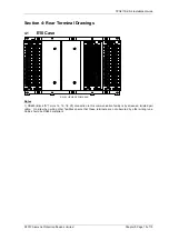
The Epsilon E10 cases provide CT shorting between terminals E23-E24, E25-E26 and E27-E28 as pairs.
Although terminals E24-E26-E28 are linked internally within the relay, these terminals must be linked externally by
panel wiring to prevent open circuit of current transformers if the relay chassis is withdrawn from the case. Check
that this wiring is present. Wipe off any dust from the outside of the relay before removing cover.
CT connections to the numeric module on terminals A13-A14. A15-A16, A17-A18, A19-A20, A21-A22, A23-A24,
A25-A26 and A27-A28 are also fitted with CT shorting contacts as pairs.
Do not open-circuit the secondary winding of a current-transformer while there is a current in its primary winding
otherwise a high voltage will be produced in the secondary which may be dangerous to personnel and may also
damage the secondary wiring insulation.

